background image

4

Maintenance


Barcode errors

34

Seahorse XFe Analyzer Operating Manual

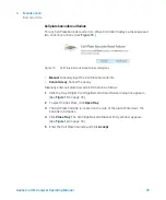
Manually enter sensor cartridge barcode

1

To display the Cartridge Barcode Manual Entry window, click 

Manual

.

2

Call the appropriate regional Agilent Cell Analysis Technical Support 
telephone number on the Cartridge Barcode Manual Entry window for 
assistance with entering the Sensor Cartridge barcode info. (See 

Figure 14

.)

Figure 14.

Cartridge Barcode Manual Entry window

Summary of Contents for Seahorse XFe

Page 1: ...Seahorse XFe Analyzer Operating Manual...

Page 2: ...e material in this document that conflict with these terms the warranty terms in the separate agreement shall control Technology Licenses The hardware and or software described in this document are fu...

Page 3: ...n to the Agilent Seahorse XFe Analyzer 2 Installation Chapter 2 provides unpacking and installation instructions for the Agilent Seahorse XFe Analyzer 3 Basic Operation Chapter 3 provides basic operat...

Page 4: ...4 Seahorse XFe Analyzer Operating Manual...

Page 5: ...tallation Procedure 17 Suitable locations for the XFe system 17 Internal components of the XFe Analyzer 18 Setup and interconnects cable installation 20 3 Basic Operation Power and Warm Up 24 Power up...

Page 6: ...6 Seahorse XFe Analyzer Operating Manual Troubleshooting 33 Barcode errors 33 Contact Information 36 Worldwide technical support 36 Ordering 36 Additional Resources 37...

Page 7: ...anual 7 1 Introduction General Information 8 Safety Considerations 9 Electrical hazards 9 Instrument Overview and Intended Use 10 Technical Specifications 11 This chapter provides an introduction to t...

Page 8: ...Analyzer Operating Manual General Information This manual covers several models of Agilent Seahorse XFe Analyzer Instrument type Model numbers 32 bit Model numbers 64 bit Seahorse XFe96 101991 100 S78...

Page 9: ...nection which is adequately rated for the load The installation must comply with local safety regulations WARNING Observe all relevant safety practices at all times If the equipment is used in a manne...

Page 10: ...centration The system measures the concentration of each analyte over time and automatically calculates the oxygen consumption rate OCR and extracellular acidification rate ECAR simultaneously in ever...

Page 11: ...0 V AC 50 60Hz Analyzer 6 A Controller 3 2 A Power cord rating 3 wire grounded AC power cord rated 10 A or greater Power fuse ratings 250 V 10 A Time delay fuses Environmental conditions Normal Enviro...

Page 12: ...1 Introduction Technical Specifications 12 Seahorse XFe Analyzer Operating Manual...

Page 13: ...ent Identification 14 Installation Procedure 17 Suitable locations for the XFe system 17 Internal components of the XFe Analyzer 18 Setup and interconnects cable installation 20 This chapter provides...

Page 14: ...by Agilent personnel during installation To prevent damage during shipping the instrument is shipped with a cartridge loaded onto the probe head and lowered onto a plate on the tray These items must b...

Page 15: ...ent Identification Seahorse XFe Analyzer Operating Manual 15 XFe Controller 32 bit OR XFe Controller 64 bit 1 1 Power cord instrument 1 Power cord controller 1 Power supply controller 1 RS232 cable 1...

Page 16: ...2 Installation Unpacking and Component Identification 16 Seahorse XFe Analyzer Operating Manual USB cable 1 USB extension cable 1 Extra fan filters 2 Instrument Component Quantity Image...

Page 17: ...e XFe system XFe Analyzers are designed for laboratory use The internal environment of the analyzer is controlled to a preset temperature by the user therefore laboratory room temperature must be main...

Page 18: ...ly See Figure 1 and Figure 2 LCD Message screen Displays current instrument action and Thermal tray temperature Cover latches Pull on indented hand holds molded into the side doors not shown to lift t...

Page 19: ...al 19 Front stripper arm Used for Sensor Cartridge removal at the end of assay runs Bar code reader Reads bar code on sensor cartridge and cell plate Circulating fan Helps to stabilize environment ins...

Page 20: ...d is used to connect the instrument to a grounded AC mains outlet A second power cord is used to connect the controller power supply module to the AC supply The power supply module is then connected t...

Page 21: ...fans circulate air through the plenum containing the heater A thermal fuse will disable the heater should it reach an abnormally high temperature Figure 5 XFe rear panel AC input power switch and ser...

Page 22: ...2 Installation Setup and interconnects cable installation 22 Seahorse XFe Analyzer Operating Manual...

Page 23: ...e 24 Performing XF assays 25 XFe status indicator 25 Wave Controller widgets 26 XFe Assays at Non 37 C Temperatures 28 Operational and assay guidelines for non 37 C assays 29 Set alarm temperature tol...

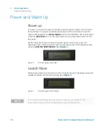
Page 24: ...t on using the power switch on the rear panel On the right side of the instrument near the access door there is an LCD message screen When the instrument is powered up the LCD message screen will show...

Page 25: ...XF data may be found online at www agilent com chem discoverXF XFe status indicator During an assay the Status Indicator light on the top of the XFe Analyzer will change from Blue to Amber if a task r...

Page 26: ...e XFe Analyzer 1 Click the Tray widget to display the Tray widget dialog box See Figure 8 2 Click Tray Out and remove the Utility Plate or Cell Plate 3 To insert the tray and maintain the Target Tempe...

Page 27: ...Seahorse XFe Analyzer Operating Manual 27 Probe control widget Use the Probes widget to load unload a Sensor Cartridge or raise lower probes To display options and select the appropriate action click...

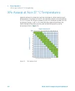
Page 28: ...ed to deliver desired target temperatures in the range of 16 42 C provided the ambient room temperature is 12 20 C below the target temperature and in the validated operational room temperature range...

Page 29: ...ration the tray heater must remain ON Do NOT turn the tray heater OFF For assay temperatures below 30 C hydrate the Sensor Cartridge in the dark at room temperature Prior to starting an assay an addit...

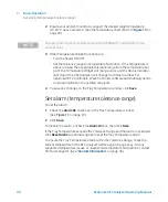
Page 30: ...lly sends an email notification to specified recipients 4 To save any changes on the Tray Temperature window click Save Set alarm temperature tolerance range To set the alarm 1 Check the Alarm On chec...

Page 31: ...intenance 32 Troubleshooting 33 Barcode errors 33 Contact Information 36 Worldwide technical support 36 Ordering 36 Additional Resources 37 This chapter provides routine maintenance troubleshooting co...

Page 32: ...the cell plate or reagents during routine use preventing cross contamination of biological or chemical materials Agilent strongly recommends an annual service contract with Preventative Maintenance to...

Page 33: ...h resolving this error and to start the assay Cartridge barcode read failure For any Sensor Cartridge barcode read errors Wave Controller displays a message and a choice of three corrective actions Se...

Page 34: ...play the Cartridge Barcode Manual Entry window click Manual 2 Call the appropriate regional Agilent Cell Analysis Technical Support telephone number on the Cartridge Barcode Manual Entry window for as...

Page 35: ...ssay Manually enter cell plate barcode information as follows 1 Click the Tray Widget Cartridge Barcode Read Failure dialog box appears See Figure 13 on page 33 2 To eject the Cell Plate click Open Tr...

Page 36: ...Phone Ordering Link to online store https www chem agilent com store US Direct Ordering Email css_afo_fax agilent com Phone 1 800 227 9770 option 1 1 Fax Purchase Orders to 302 633 8901 Europe Contac...

Page 37: ...library usermanuals public Wave_2_ 6_User_Guide pdf Software Download Page https www agilent com en support cell analysis seahorse xf so ftware XFe Consumables Web Page https www agilent com en produ...

Page 38: ...4 Maintenance Additional Resources 38 Seahorse XFe Analyzer Operating Manual...

Page 39: ......

Page 40: ...www agilent com Agilent Technologies Inc 2018 Second Edition June 2018 S7804 90001 S7804 90001_REV A...

Reviews: