background image

SureScan System User Guide

39

Creating and Changing Scan Regions

The 

scan region

 determines the area of the slide that is scanned. The larger the region, the longer 

the scan time. If you use non-Agilent slides, you can create your own scan region or change a 
scan region, up to the maximum scan region of 71 mm x 21.6 mm. The new region appears as a 
selection in the slot table and in the Protocol Editor.

To create a scan region

Make sure that the scan region is at least 4 mm away from the barcode label and does not 
overlap any other opaque or translucent areas of the slide.

1

In the Scan Control program menu bar, click 

Tools > Scan Region Editor

.

The Scan Region Editor opens.

2

In the list next to 

Scan Region

, select 

New Scan Region

.

Or
To use an existing scan region as a template,

a

In the list next to 

Scan Region

, select one of the available scan regions.

b

Select 

Save As

.

The Save As New Name dialog box opens.

c

Type the name for the new scan region, and then click 

OK

.

The scan region settings become active.

3

Under 

Scan Region

, type the measurements (in mm) for the region. If you type an invalid value, 

a red box appears around the measurement.
The red box at the top of the dialog box shows the scan region currently defined.

4

Click 

Save

.

If no errors are found, the Scan Region Editor appears with the new region listed in the Scan 
Region Editor. 

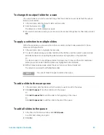
Change an existing scan region for non-Agilent slides

You can only change the scan regions that you created. You cannot change or remove the regions 
provided by Agilent.

When creating a scan region or using existing scan regions, make sure that the scan region is at 
least 4 mm away from the barcode label.

1

In the Scan Control program menu bar, click 

Tools > Scan Region Editor

.

The Scan Region Editor opens.

2

In the list next to 

Scan Region

, select the scan region you want to modify.

3

Change the measurements for the region, as desired. For more information on the settings 
available, see 

“Scan Region Editor dialog box” 

on page 82.

Summary of Contents for SureScan G4900DA

Page 1: ...Agilent G4900DA SureScan Microarray Scanner System Microarray Scan Control Software 9 1 User Guide For Research Use Only Not for use in diagnostic procedures Revision B0 September 2019...

Page 2: ...warranty terms in the separate agreement shall control Technology Licenses The hardware and or software described in this documentarefurnishedunderalicenseandmay be used or copied only in accordance w...

Page 3: ...Microarray Scan Control program 3 Using the Scan Control Program This chapter describes how you use the Scan Control program to set up and run the scanner 4 Using Scan Control Tools In this chapter l...

Page 4: ...puter Workstation 15 2 Getting Started 16 Operating the Scanner 17 Step 1 Turn on the SureScan scanner and start the Scan Control program 17 Step 2 Insert slides into slide holders 19 Step 3 Load the...

Page 5: ...Creating and Changing Scan Protocols 36 To create a scan protocol 36 To change an existing scan protocol 36 To export a scan protocol 37 To import a scan protocol 37 To remove a scan protocol 38 Crea...

Page 6: ...eshooting 54 Software Troubleshooting 55 File locations 56 System error messages 56 Using the Diagnostic Display 62 Updating the Scanner Firmware and Scan Control Program 63 To check if an update is a...

Page 7: ...ettings dialog box Design To Protocol Mapping 85 About Adding Slides 87 Performing Feature Extraction on Scanned Images 88 SureScan Scanner Specifications 89 Slide Specifications 91 Scan dimensions 91...

Page 8: ...8 1 Introduction A Powerful Tool for Microarray Analysis 9 System Description 10 Principles of Operation 14 Programs Installed on the Computer Workstation 15 This chapter provides a general introduct...

Page 9: ...ted on standard 1 in 3 in slides The scanner measures the fluorescence intensity of labeled sample nucleic acid DNA and RNA bound to microarrays Its ability to measure fluorescence from two dyes simul...

Page 10: ...cient of Variation TIFF image file compression Flip and rotate images Internal and external barcode reading The Agilent Microarray Scan Control program allows you to select the dye fluorescence channe...

Page 11: ...bit Professional or Windows 10 64 bit Pro operating system Hardware Intel Core 2 Duo E8500 3 16 GHz or equivalent 8 GB RAM Minimum 250 GB hard disk Proper disk maintenance is required to ensure that y...

Page 12: ...plug LAN connector Laser cooling air outlet Laser cooling air inlet Main cooling air outlet Main cooling air inlet Power supply air outlet WARNING Do not attempt to repair or gain access to SureScan s...

Page 13: ...The SureScan scanner is sensitive to condensing humidity conditions Follow precautions stated in product documentation See Tips to prevent problems on page 51 of Chapter 5 and the relative humidity s...

Page 14: ...to the microarray probes Dyes similar to Cy 3 and Cy 5 such as Alexa 647 555 and 660 dyes can also be used The SureScan scanner is optimized for high signal to noise performance in the Cy 3 550 610 nm...

Page 15: ...the scanner Agilent Feature Extraction program automatically performs feature extraction using scanned image files created by the scanner You can also run the Feature Extraction program manually to e...

Page 16: ...holders into the cassette 21 Step 4 Set or change protocol scan settings 23 Step 5 Add slides to the scan queue 23 Step 6 Scan your slides 24 Step 7 Remove the slides 24 About Scan Protocols 25 Offlin...

Page 17: ...igure 4 Agilent Microarray Scan Control icon When the program starts the Agilent Microarray Scan Control program main window opens and the scanner performs its initialization sequence See Scan Control...

Page 18: ...is finished the Open Door button is enabled and the lasers continue to warm up WarmUp The lasers typically take less than 30 seconds to warm up During warm up you can load slides set protocols and add...

Page 19: ...ning the slide holder Figure 7 Inserting slide into the slide holder 3 Insert the slide into the holder as follows a Hold the slide at the barcode end b Make sure that the active microarray surface fa...

Page 20: ...plastic slide cover pushing on the tab end until you hear it click See Figure 9 Figure 8 Slide inserted in slide holder Figure 9 Slide holder closed with slide For instructions on removing the slides...

Page 21: ...slide holders you can load the slide holders into the cassette The cassette and slide holders are designed to ensure that the slide holders are inserted correctly Figure 11 Slide holder helps you to i...

Page 22: ...2 and 3 until all slide holders are loaded in the cassette The slide numbers next to the cassette and in the slot table of the Scan Control program window change color to indicate the state of the slo...

Page 23: ...de 1 For each slide in the slot table click the Scan Protocol and select a scan protocol to use for scanning the slide See About Scan Protocols on page 25 and To set or change the scan protocol on pag...

Page 24: ...can progress for example Scanning 50 is displayed in the slot State The remaining scan time and required disk space are displayed at the bottom of the Scan Control main window See Scan Control Program...

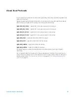
Page 25: ...GX 2 color gene expression microarrays AgilentG3_GX_1Color Agilent GX 1 color gene expression microarrays AgilentHD_CGH Agilent HD CGH CNV ChIP microarrays AgilentG3_CGH Agilent G3 CGH CNV ChIP micro...

Page 26: ...trument is available the Scan Control program runs in offline mode In this mode you can create import and export scan protocols and scan regions You can also open log files display recent errors set g...

Page 27: ...the scanner cassette 4 Remove the slides from the slide holders 5 Click Close Door 6 In the Scan Control main window click the red X at the upper right corner to close the program The lasers are turn...

Page 28: ...scanner door 32 To start a scan 32 Changing Slide Scan Settings 33 To change settings for a single slide 33 To change settings for multiple slides 33 To add a description for the slide 34 To add a use...

Page 29: ...reads the barcode for a slide and displays it as the Slide ID in the slot table To add or change the Slide ID in the table follow the instructions below 1 In the slot table click the Slide ID cell for...

Page 30: ...a second slide All slides between and including the selected slides are highlighted in the slot table Or To select a series of noncontiguous slides hold down the Ctrl key and then click additional sl...

Page 31: ...the slide down one position To remove a slide from the scan queue 1 In the slot table click the State cell for the slide you want to remove from the queue 2 Click again to show selections for the sli...

Page 32: ...click Start Scan The slot status indicator light blinks green during the scan process The scan progress for example Scanning 50 is displayed in the slot State cell NOTE You must close the door before...

Page 33: ...ble select the slide whose settings you want to change 2 In the Scan Settings area click the arrow next to the setting you want to change and then select the new setting When you manually change a set...

Page 34: ...State cell and add the slide to the queue See To add a slide to the scan queue on page 30 To add a user name You can only change the user name for a slide when it is not in the scan queue See To remo...

Page 35: ...the Scan Control program provides general settings and functions that help with troubleshooting Scan control tools let you Create or change scanner protocols Change the scanning region for slides Inp...

Page 36: ...me The Save As New Name dialog box opens 4 Type a new name for the protocol and then click Save The scan protocol settings become active 5 Change the scan and image settings as desired For information...

Page 37: ...Click to select a protocol and then hold down the Ctrl key and select additional noncontiguous protocols to export 4 Click Export The Save As dialog box appears 5 Browse to the location where you wan...

Page 38: ...ools Scan Protocol Editor The Scan Protocol Editor dialog box opens 2 In the Scan Protocol list select a protocol to remove 3 Click Remove NOTE You cannot remove any of the default protocols or any pr...

Page 39: ...New Name dialog box opens c Type the name for the new scan region and then click OK The scan region settings become active 3 Under Scan Region type the measurements in mm for the region If you type an...

Page 40: ...en hold down the Shift key and then click to select the last scan region to export 4 Click Export 5 The Save As dialog opens 6 Browse to the location where you want to save the exported scan region fi...

Page 41: ...Click Tools Scan Region Editor The Scan Region Editor dialog box opens 2 In the Scan Region list select a scan region to remove 3 Click Remove NOTE You cannot remove any of the default scan regions o...

Page 42: ...a slide already in a slot is unreadable remove the slide holder that contains the slide from the cassette 3 In the Scan Control main window click Tools Input Barcode The Input Barcode dialog box opens...

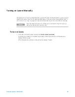
Page 43: ...laser saver delay on page 46 This section describes how to turn on the lasers manually To turn on lasers In the Scan Control program window click Tools Switch on Lasers The lasers are turned on The S...

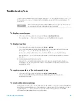
Page 44: ...t affect the software execution 2 Double click to select and open a log file Files with the csv comma separated variable extension are opened by default with an available spreadsheet program Files wit...

Page 45: ...r local Agilent sales and support center To reset calibration warnings In the Scan Control menu bar click Tools Reset Calibration Warnings To run a self test 1 In the Scan Control menu bar click Tools...

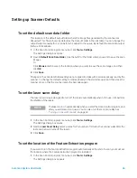
Page 46: ...he default setting for slides already in the slot table open and then close the scanner door so that the scanner reads the barcodes again To set the laser saver delay The laser saver delay is designed...

Page 47: ...e 3 Click Save To select to run Feature Extraction after scanning You can select to run the Feature Extraction program automatically at the end of a scan For more information see Settings dialog box G...

Page 48: ...Control program menu bar click Tools Settings The Settings dialog box opens 2 Click the Design to Protocol Mapping tab 3 Under Design ID type the Design ID number for the design you want to assign to...

Page 49: ...ystem 52 Technical Support 52 Frequently Asked Questions FAQs 53 Hardware Troubleshooting 54 Software Troubleshooting 55 System error messages 56 Updating the Scanner Firmware and Scan Control Program...

Page 50: ...e performance of your computer workstation and operating system At least once a week check disk space and archive data as needed Once a week delete any temporary files mp tmp files from the C Temp fol...

Page 51: ...Specifications on page 89 Control the humidity The scanner is sensitive to condensing humidity conditions To ensure optimal performance operate the scanner only in the specified humidity ranges See S...

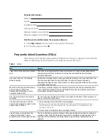
Page 52: ...ck Help Online Support SureScan Microarray Scanner System support If you have a problem with your SureScan Microarray Scanner System that requires assistance from your local Agilent sales and support...

Page 53: ...ing is included in the scan log Where do I find support information such as drivers guides and troubleshooting solutions for my computer workstation If you have a problem with your computer workstatio...

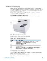
Page 54: ...anner Figure 13 Location of the status indicator light Table 2 describes the possible states of the indicator light Checking and replacing scanner fuses The scanner has two fuses for the power supply...

Page 55: ...e fuse with a T4A 250 VAC rated fuse part number 2110 1491 5 Push the fuse holder back in until it clicks into place 6 Plug in the power cord Software Troubleshooting In case you experience a computer...

Page 56: ...ut Folder in the Slot Table to C ProgramData Agilent MicroArrayScanner Temp System error messages This section explains how to use error messages and error logs generated by the SureScan Microarray Sc...

Page 57: ...tion A slide has been placed in the active slot Slot number Remove the slide to allow scanning to continue A slide is currently in the active slot and the scanner cannot return the scanned slide to it...

Page 58: ...d Scan Control program installation is corrupt Reinstall the Scan Control program Load test script set failed Reinstall the Scan Control program Open Online Support website failed Web page is currentl...

Page 59: ...calibration completed with warnings Indicates data system calibration failure If the problem persists call service Data system calibration failed Indicates data system calibration failure If the prob...

Page 60: ...nstrument operation suspended Check ventilation slots PMT calibration failed Indicates PMT calibration failure If the problem persists call service Red Laser power is not set to calibrated value Laser...

Page 61: ...problem do the following a Close the Scan Control program a Restart the computer workstation b Turn off the scanner and then back on c Restart the Scan Control program 4 If step 3 does not solve the...

Page 62: ...trument the display shows the IP address of the scanner If the IP address is not displayed the firmware is not running Toggle the switch Up to cycle through a menu with the following choices The first...

Page 63: ...ram and firmware 1 From the Scan Control main window click Help Scanner Home Page The Agilent Technologies Genomics High Resolution Scanner Overview web page opens 2 In the web page click Download Sof...

Page 64: ...ram after updating your software to verify that the update installed correctly 1 Click Start All Programs Agilent Technologies Installation Qualification Tool Figure 16 Agilent Installation Qualificat...

Page 65: ...x Reference 74 About Adding Slides 87 Performing Feature Extraction on Scanned Images 88 SureScan Scanner Specifications 89 Slide Specifications 91 Regulatory Information 94 This chapter includes desc...

Page 66: ...ow The Microarray Scan Control window appears when you start the Microarray Scan Control Program It has the following features Menu bar Slot table Function buttons Settings pane Logs Status bar Slot s...

Page 67: ...k space required for the scan Table 5 Scan Control window features Feature Description Table 6 Scan Control Tools commands Tool Description Scan Protocol Editor Opens the Scan Protocol Editor dialog b...

Page 68: ...the warm up period If this problem occurs the system sets the warning and recalibrates the lasers at 80 of their specified power Use this function to reset the warnings to default settings Self Test...

Page 69: ...oor the program reads the barcode label for each slide in the cassette and displays it in this column You can change the Slide ID to any text acceptable in a file name The barcode for the slide is ret...

Page 70: ...m the cassette Blinks yellow Replaced A slide was placed into a slot whose state was Removed If the barcode matches the original slide that was removed the State is changed back to Ready or In Queue I...

Page 71: ...o select a network folder If a network access problem is experienced during the scan data is saved to a temporary local folder and a warning is included in the scan log Function buttons Buttons next t...

Page 72: ...gs Some data analysis programs have specific requirements for the images This section lets you change how the image is created from the scan For more information see Image Settings on page 80 File Nam...

Page 73: ...menu with the following options Table 10 Shortcut menu options for log tabs Menu command Description Clear Clears the contents of the tab The contents of the log file is not affected Copy Active afte...

Page 74: ...fication report includes a list of all files verified as OK Default is not selected Invalid files are always shown Open report after qualification When selected the qualification report opens in your...

Page 75: ...se Lets you select available scan protocols to export To open In the Scan Protocol Editor dialog box click Export Export When one or more scan protocols are selected this command opens the Save As dia...

Page 76: ...ort When one or more scan regions are selected this command opens the Save As dialog box where you select a location and file name for the exported scan regions file Close Closes the dialog box Input...

Page 77: ...slot 1 Close Used to close the dialog box Scan Protocol Editor dialog box Figure 28 Scan Protocol Editor dialog box Purpose Used to create or change scan protocols To open In the Scan Control program...

Page 78: ...5 3 and 2 micron scans you can select double pass scanning to perform this averaging or acquire only a single scan line for each image row A high sensitivity scan mode is also available at all scan r...

Page 79: ...capture the wide dynamic range of data With the XDR function turned on the scanner automatically scans the same slide twice at two different PMT sensitivity levels It generates two linked images that...

Page 80: ...wing rules For standard scans the Scan Control program uses up to three user defined name prefixes to compose the file name These prefixes are defined in the scan protocol Field1_Field2_Field3_ScanNum...

Page 81: ...h is found the scan number is increased until the file name is unique Example US4510PP02_251485023883_S03 tif Instrument Serial US4510PP02 Slide ID 251485023883 ScanNumber S03 Indicates the third scan...

Page 82: ...egion Editor General Agilent Defined A protocol provided by Agilent Locked When a protocol is locked it cannot be changed Scan Region TopLeft X X axis measurement for the upper left corner Type this m...

Page 83: ...Save As New Name dialog box where you can save the current scan region with a new name Remove Removes the selected scan region This button is unavailable if the scan region is an Agilent defined scan...

Page 84: ...ettings that require a folder location lets you browse to the folder and select it rather than typing the path Save Saves the settings If you change settings and want to save them select this button b...

Page 85: ...g tab Purpose Used to assign default scan protocols to microarray slide Design IDs Whenever the scanner recognizes a slide that has a scan protocol mapped to its design the program automatically fills...

Page 86: ...otocol that is assigned to the Design ID This scan protocol is automatically assigned in the Slot Table whenever the scanner recognizes a slide with the associated Design ID Description An area where...

Page 87: ...s to finish When the door is open the scanner waits to eject a slide that is currently scanning If the door is left open with no activity for 5 minutes a message appears to warn you that the door is a...

Page 88: ...e image or you must have the Feature Extraction program configured to use the eArray server during extraction Run the Feature Extraction program manually after the scanned images are created For infor...

Page 89: ...hipping box Altitude Operating maximum 4 600 m 15 000 ft Storage maximum 9 200 m 30 000 ft at 40 C Usage Indoor use Laser information Wavelengths Green solid state laser 532 nm Red solid state laser 6...

Page 90: ...e for Single and Double Pass Scans for Agilent HD Scan Region 61 x 21 6 mm Resolution Scan Time min 2 micron single pass 24 3 micron single pass 16 5 micron single pass 10 10 micron single pass 10 2 m...

Page 91: ...ece of glass The detailed specifications of the glass are as follows 1 inch wide 25 4 mm 0 45 mm or 0 7 mm 3 inches long 76 2 mm 0 25 mm or 1 4 mm 1 mm thick 0 1 mm No mirrored slides High quality wit...

Page 92: ...4 mm Figure 36 Barcode label location on non Agilent slide The barcode label width should be about 6 mm the recommended barcode label width is for use with the 61 mm scan region Larger or longer barco...

Page 93: ...ight digits minimum line thickness 6 mils Code 39 Maximum of eight digits minimum line thickness 6 mils Code 93 Maximum of eight digits minimum line thickness 6 mils Minimum height of barcode must be...

Page 94: ...ng and disposal This device is designed to accommodate recycling at the end of its useful life Please dispose of this device in accordance with local regulations Contact Agilent Technologies for more...

Page 95: ...Requirements for Electrical Equipment for Measurement Control and Laboratory Use Part 1 General Requirements IEC 61010 1 2001 Safety Requirements for Electrical Equipment for Measurement Control and...

Page 96: ...e agilent com For all other regions Agilent s world wide sales and support center telephone numbers can be obtained at www agilent com under Contact Us Or send an email to genomics agilent com Agilent...

Reviews: