17
Technical Information
Interconnections
178/224
TV 301-P Navigator Controller User Manual
/ 87-901-001-01 (B)
Interconnections
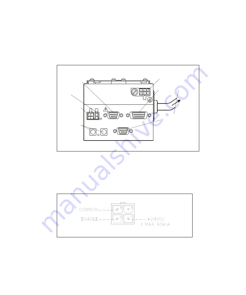
The following figure shows the TV 301-P interconnections.
Figure 2
Interconnections
P3 – Vent
Figure 3
P3 – Vent
This is a dedicated 24 Vdc connector to control the optional vent
valve.
J6 SERIAL
P5
FAN
P3
VENT
LD1
STATUS
J5 IN-OUT
MAINS
FUSE TYPE
250V T 8A
STATUS
ADDRESS
MSD
LSD
J2 PROFIBUS
EXTERNAL
FAN
SERIAL LINE
IMPUT/OUPUT LINE
PROFIBUS LINE
TO PUMP
MAINS POWER
VENT VALVE
ADDRESS
STATUS
Summary of Contents for TV 301-P
Page 4: ...TV 301 P Navigator Controller 4 224 TV 301 P Navigator Controller User Manual 87 901 001 01 B ...
Page 12: ...Contents 12 224 TV 301 P Navigator Controller User Manual 87 901 001 01 B ...
Page 219: ......
Page 220: ......
Page 221: ......
Page 222: ......
Page 223: ......


