302
Appendix B
Differences from Agilent 4286A
3. Functional Differences Between 4286A and 4287A
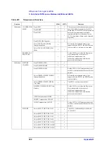
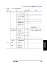
Calibration
CALIBRATION
MENU
Run OPEN
√
√
The concept of calibration/compensation for
the 4286A differs from that for the 4287A.
In addition, for the 4286A, the compensation
data for Rdc measurement is obtained
together with that for calibration; for the
4287A, these kinds of data can be obtained
separately.
Run SHORT
√
√
Run LOAD
√
√
Run LOW-LOSS Capacitor
√
√
Select CAL POINT [FIXED]
Interpolation Mode
√
Because the interpolation mode is not
supported for the 4287A, the FIXED mode
is not available; it is always in user mode.
Select CAL POINT [USER] User
Mode
√
√
RESUME CAL
SEQUENCE
√
√
For the 4287A, even when the Run screen
closes temporarily in the course of
calibration/compensation, the
calibration/compensation data already
processed is not cleared.
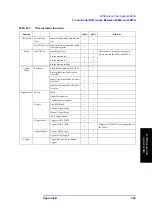
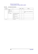
Calibration
FIXTURE
COMPEN
Run COMPEN OPEN
√
√
Run COMPEN SHORT
√
√
Run COMPEN LOAD
√
For the 4287A, LOAD compensation is not
available; calibration should be used for this
purpose.
Select COMPEN POINT [FIXED]
Interpolation Mode
√
Because the interpolation mode is not
supported for the 4287A, the FIXED mode
is not available.
Select COMPEN POINT [USER]
User Mode
√
√
The 4287A is always in user mode.
RESUME COM SEQUENCE Data
Resume
√
√
For the 4287A, even when the Run screen
closes temporarily in the course of
calibration/compensation, the
calibration/compensation data already
processed is not cleared.
OPEN Compensation ON/OFF
√
√
SHORT Compensation ON/OFF
√
√
LOAD Compensation ON/OFF
√
For the 4287A, LOAD compensation is not
available; calibration should be used for this
purpose.
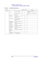
FIXTURE
Select SELECT FIXTURE 16191
√
√
The 4287A is additionally provided with
16196A/B/C.
Select SELECT FIXTURE 16192
√
√
Select SELECT FIXTURE 16193
√
√
Select SELECT FIXTURE 16194
√
√
Select SELECT FIXTURE 16196A
√
Select SELECT FIXTURE 16196B
√
Select SELECT FIXTURE 16196C
√
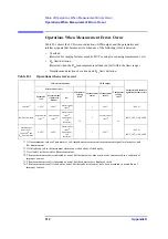
Table B-5
Measurement functions
Function
4286A
4287A
Remarks
Summary of Contents for Twelfth 4287A RF LCR
Page 8: ...8...
Page 36: ...36 Chapter2 Installation Guide Preparation for Power Supply Figure 2 17 Power cable options...
Page 114: ...114 Chapter5 Setting Measurement Conditions Setting up dc resistance Rdc measurement...
Page 250: ...250 Chapter11 Setting and Using the Control and Management Facilities System Recovery...
Page 294: ...294 AppendixA Manual Changes Manual Changes...
Page 328: ...328 AppendixF Error Messages Undefined header...


