Chapter 3
59
Learning Basic Operations
Calibration and Compensation
3. Lea
rn
ing Basic
O
p
er
at
ion
s
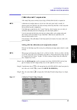
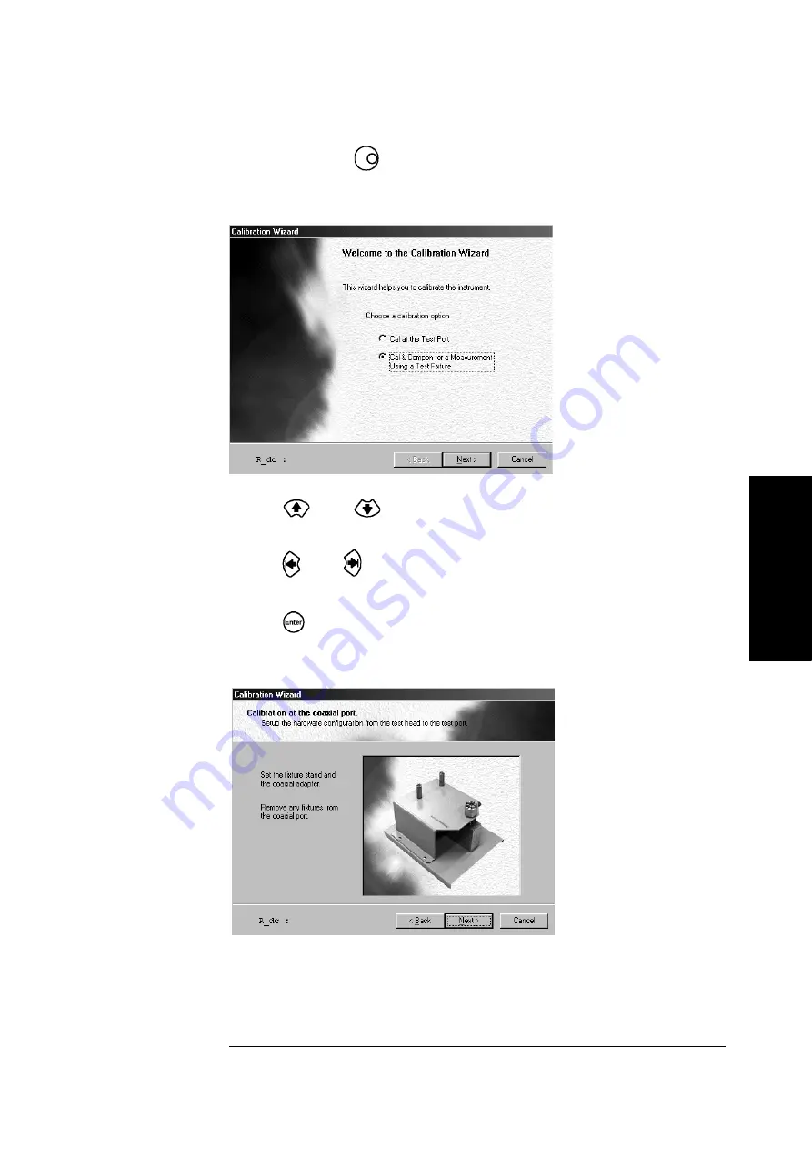
Step 2.
Press the rotary knob (
) to display the calibration and compensation wizard welcome
window (Figure 3-10).
Figure 3-10
Calibration and compensation wizard welcome window
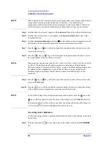
Step 3.
Press the
key or
key on the front panel to select the
Cal/Compen for a Fixture
Measurement
option (
) (filled circle should appear inside the radio button).
Step 4.
Press the
key or
key on the front panel the required number of times to move the
cursor to the
Next>
button.
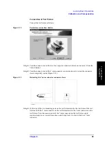
Step 5.
Press the
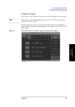
key on the front panel. The window for setting up the test head and test
fixture stand (Figure 3-11) appears.
Figure 3-11
Display for setting up test head and test fixture stand
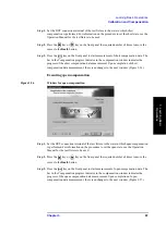
Step 6.
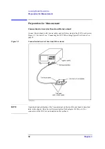
Confirm that the setup has been performed as shown in Figure 3-2, “Connection between
test head and fixture stand,” on page 52 (in this condition nothing should be connected to
the 7-mm terminal).
Summary of Contents for Twelfth 4287A RF LCR
Page 8: ...8...
Page 36: ...36 Chapter2 Installation Guide Preparation for Power Supply Figure 2 17 Power cable options...
Page 114: ...114 Chapter5 Setting Measurement Conditions Setting up dc resistance Rdc measurement...
Page 250: ...250 Chapter11 Setting and Using the Control and Management Facilities System Recovery...
Page 294: ...294 AppendixA Manual Changes Manual Changes...
Page 328: ...328 AppendixF Error Messages Undefined header...

