Chapter 4
93
Function Overview
Names and Functions of Display Areas on the LCD Display
4.
F
u
nct
ion
O
v
e
rv
iew
Calibration kit setup display
When no dialog box is shown, the calibration kit setup display (Figure 4-8) can be
displayed by pressing the
[Setup View]
key the required number of times.
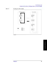
Figure 4-8
Calibration kit setup display
1. Calibration kit setup tab
When the “CAL KIT” tab is displayed in front of the other three tabs, the screen shows the
calibration kit setup display. If another setup display appears, click this tab with the mouse
to get the calibration kit setup display. (The same operation can be done with the “View”
menu in the menu bar.)
2. Calibration kit selection
You can choose whether to use the values predetermined for the 7-mm calibration kit
(7-mm standard) or user-defined values as a calibration kit definition. To use the Agilent
Technologies 16195B 7-mm calibration kit, select “7 mm Standard.”
Before selecting “7 mm Standard,” all calibration kit values should have been entered; the
user is not allowed to change the definition.
If you select “User Defined,” you can freely enter the values for the calibration kit
definition. If you check (
√
) “Fixed Model,” enter the definition for measurement point
number 1, which is then automatically applied to the other measurement point numbers.
3. Measurement point number/measurement frequency
Displays the measurement points (measurement point number and measurement
frequency) in the selected measurement point table.
Summary of Contents for Twelfth 4287A RF LCR
Page 8: ...8...
Page 36: ...36 Chapter2 Installation Guide Preparation for Power Supply Figure 2 17 Power cable options...
Page 114: ...114 Chapter5 Setting Measurement Conditions Setting up dc resistance Rdc measurement...
Page 250: ...250 Chapter11 Setting and Using the Control and Management Facilities System Recovery...
Page 294: ...294 AppendixA Manual Changes Manual Changes...
Page 328: ...328 AppendixF Error Messages Undefined header...


