Chapter 6
123
Calibration and Compensation
Calibration and Compensation Procedures Using Dedicated Test Fixture
6. Calibration
and
Comp
ensatio
n
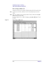
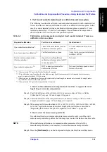
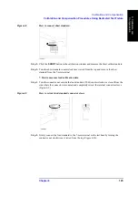
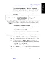
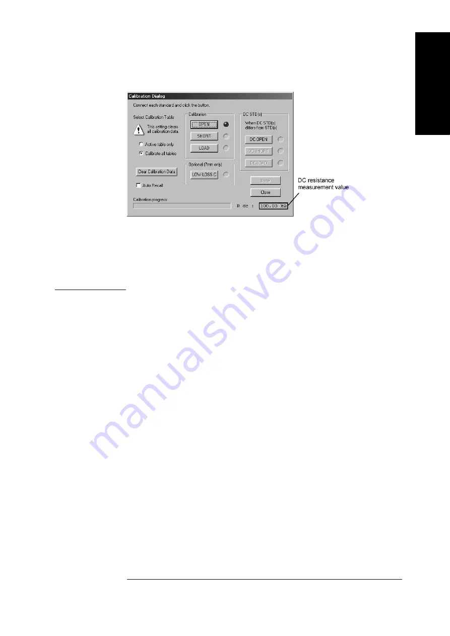
Figure 6-5
Displaying measured DC resistance value (at calibration data measurement)
•
To erase all calibration data after measurement is finished, press the Clear Calibration
Data button.
•
To close the dialog box during calibration, press the
Close
button.
•
After turning all of the connector nuts on the standard to secure them to the 7-mm
terminals, it is not necessary to turn the connector nut of the 7-mm terminal of the test
head to secure it.
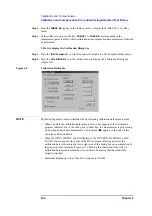
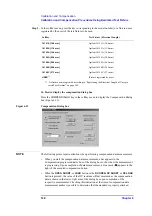
4. How to select the table range for executing the calibration
Select the table range for executing the calibration by making the appropriate setting in the
Select Calibration Table
area of the Calibration Dialog box window.
If you select
Active table only
, calibration will be executed only for the measurement
point table (active table) selected according to “How to select the measurement point table”
on page 115.
When you select
Calibrate All Tables
, calibration will be executed for all measurement
point tables.
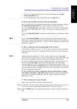
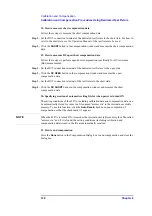
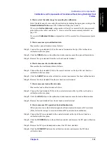
5. How to measure open calibration data
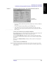
Step 1.
With the test head mounted on the test fixture stand, turn the outer connector nut of the
7-mm connector clockwise as viewed from the top (Figure 6-6) until the connector sleeve
is fully extended.
Summary of Contents for Twelfth 4287A RF LCR
Page 8: ...8...
Page 36: ...36 Chapter2 Installation Guide Preparation for Power Supply Figure 2 17 Power cable options...
Page 114: ...114 Chapter5 Setting Measurement Conditions Setting up dc resistance Rdc measurement...
Page 250: ...250 Chapter11 Setting and Using the Control and Management Facilities System Recovery...
Page 294: ...294 AppendixA Manual Changes Manual Changes...
Page 328: ...328 AppendixF Error Messages Undefined header...


