Chapter 6
151
Calibration and Compensation
Preventing Mistakes During Execution of Calibration and Compensation
6. Calibration
and
Comp
ensatio
n
Preventing Mistakes During Execution of Calibration and
Compensation
Setting limit values for the DC resistance (Rdc) measurement value when calibration and
compensation are executed makes it possible to detect an improperly attached standard
during calibration or any abnormality with the measurement terminals during
compensation.
1. Setting the limit for DC resistance (Rdc)
Step 1.
Press the
[Cal/Compen]
key on the front panel to display the Cal/Compen softkey menu.
Step 2.
Press the
SETUP CAL WIZARD
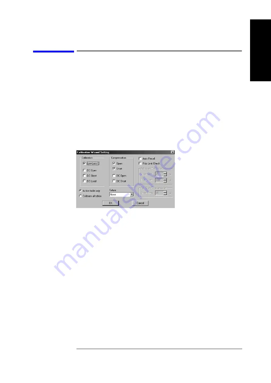
key in the softkey menu to display the
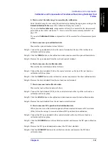
Calibration/Compensation Wizard Setting dialog box (Figure 6-23).
Figure 6-23
Calibration/Compensation Wizard Setting dialog box
Step 3.
The following settings should be made in the Calibration/Compensation Wizard Setting
dialog box:
•
In the
Calibration
area, select the calibration to be performed in addition to
Open/Short/Load calibration.
•
In the
Compensation
area, select the compensation to be executed.
•
For the measurement point table range for which calibration and compensation should
be performed, select either
Active table only
or
Calibrate all tables
.
•
Select the test fixture to be used from the
Fixture
area.
•
To automatically store the setting conditions of the 4287A and the calibration and
compensation data in the “autorec.sta” file upon completion of the
calibration/compensation, click the
Auto Recal
l
check box so that the check mark (
√
)
appears.
Step 4.
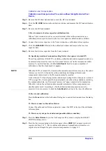
Click the
Rdc Limit Check
check box in the Calibration/Compensation Wizard Setting
dialog box so that the check mark (
√
) appears, thus turning on the DC resistance (Rdc)
limit check when calibration and compensation is performed (Figure 6-24).
Summary of Contents for Twelfth 4287A RF LCR
Page 8: ...8...
Page 36: ...36 Chapter2 Installation Guide Preparation for Power Supply Figure 2 17 Power cable options...
Page 114: ...114 Chapter5 Setting Measurement Conditions Setting up dc resistance Rdc measurement...
Page 250: ...250 Chapter11 Setting and Using the Control and Management Facilities System Recovery...
Page 294: ...294 AppendixA Manual Changes Manual Changes...
Page 328: ...328 AppendixF Error Messages Undefined header...

