Chapter 4
77
Function Overview
Names and Functions of Parts on the Front Panel
4.
F
u
nct
ion
O
v
e
rv
iew
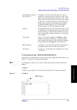
8. Test Head Interface (TEST HEAD INTERFACE)
This interface includes the three ports used to connect the test head: RF OUT, PORT 1, and
PORT 2. All ports are N-type connectors (female).
NOTE
Do not apply DC voltage or DC current to the test head interface as this could result in
damage.
Test Head
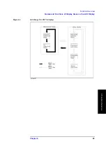
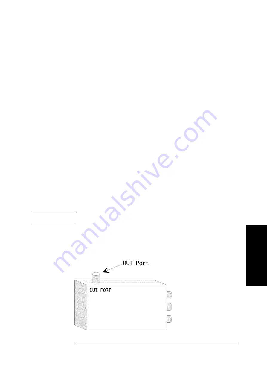
The DUT port (see Figure 4-2) corresponds to the IEC61010-1 installation category I.
Figure 4-2
Test Head
[G/n][M/
μ
][k/m] and [
×
1]
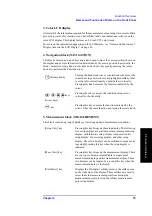
keys (unit keys)
Pressing one of these keys after the numerical value is
entered by a numeric entry key confirms your entry of the
input numerical value assigned to the unit. In other words,
these keys execute the setup. Only two prefixes are labeled
on the surface of each key, and the selection of the prefix
and the type of the unit are automatically determined in
conformity with the parameter to be set. The
[
×
1]
key
allows the setup to be executed without any prefix.
[Alt] key
Pressing this key allows you to use the menu bar at the top
of the display screen without using the mouse. Then use the
numeric entry keys to enter the menu number you want to
select or operate the navigation block keys to your desired
menu/submenu.
[Cancel] key
This key uses the same hardkey as the
[Alt]
key. When a
dialog box is displayed and this key is pressed, settings
made using this dialog box are cancelled (the key performs
the same function as the
Cancel
key in the dialog box).
[Back Space] key
Use this key to erase one character of the entered character
string immediately to the left of the cursor position.
[Preset] key
Use this key to set the 4287A to an initialized state called
“Preset state.”
Summary of Contents for Twelfth 4287A RF LCR
Page 8: ...8...
Page 36: ...36 Chapter2 Installation Guide Preparation for Power Supply Figure 2 17 Power cable options...
Page 114: ...114 Chapter5 Setting Measurement Conditions Setting up dc resistance Rdc measurement...
Page 250: ...250 Chapter11 Setting and Using the Control and Management Facilities System Recovery...
Page 294: ...294 AppendixA Manual Changes Manual Changes...
Page 328: ...328 AppendixF Error Messages Undefined header...


