92
Chapter 4
Function Overview
Names and Functions of Display Areas on the LCD Display
the measurement point setup display. If another setup display appears, click this tab with
the mouse to get the measurement point setup display. (The same operation can be done
with the “View” menu in the menu bar.)
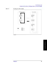
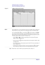
3. Measurement point number
This number indicates the measurement point. Measurement is done in the order of these
measurement point numbers as described in “List measurement display” on page 89.
NOTE
Measurement is enabled at the measurement point when the measurement conditions
(measurement frequency, averaging factor, oscillator level) are entered.
Measurement points must be set up sequentially starting from point 1.
4. Measurement frequency
Enter the measurement frequency for each measurement point.
5. Averaging factor
Enter the averaging factor for each measurement point.
6. Test signal level
Enter the test signal level for each measurement point.
7. Oscillator level setup unit
Select the unit used for setting as described in “6. Test signal level”. You can select one of
the following oscillator level setup units for each table: dBm, V (volt) or A (ampere).
8. Measurement point table selection buttons
Click one of these eight buttons with the mouse to display the contents of the
corresponding measurement point table. (The same operation can be done with the “Table”
menu in the menu bar.) The currently selected measurement point table is highlighted.
9. Setup display exit button
Click this button with the mouse to close the setup display and return to the measurement
display.
NOTE
The “8. Measurement point table selection buttons” and “9. Setup display exit button”
displayed at the bottom of the setup display are together referred to as the “tool bar,” which
can be toggled between displayed and hidden states with the “ToolBar” menu item in the
menu bar’s “View” menu.
Summary of Contents for Twelfth 4287A RF LCR
Page 8: ...8...
Page 36: ...36 Chapter2 Installation Guide Preparation for Power Supply Figure 2 17 Power cable options...
Page 114: ...114 Chapter5 Setting Measurement Conditions Setting up dc resistance Rdc measurement...
Page 250: ...250 Chapter11 Setting and Using the Control and Management Facilities System Recovery...
Page 294: ...294 AppendixA Manual Changes Manual Changes...
Page 328: ...328 AppendixF Error Messages Undefined header...


