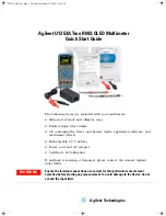
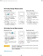
U1253A Quick Start Guide
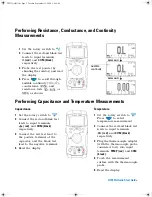
Performing Resistance, Conductance, and Continuity
Measurements
Performing Capacitance and Temperature Measurements
1
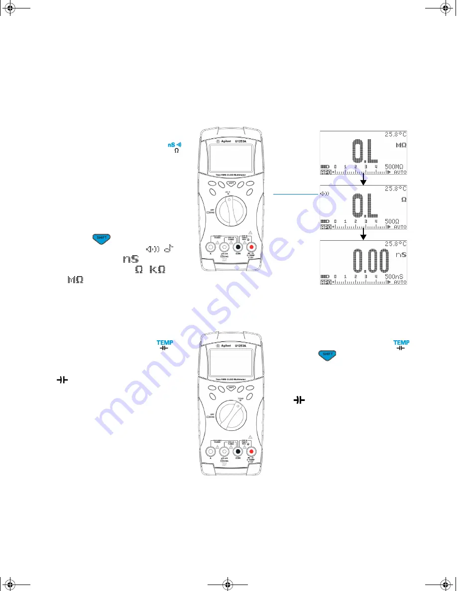
Set the rotary switch to
.
2
Connect the red and black test
leads to input terminals
Ω
(red)
and
COM (black)
respectively.
3
Probe the test points (by
shunting the resistor) and read
the display.
4
Press
to scroll through
audible continuity (
/
),
conductance (
), and
resistance tests (
,
, or
) as shown.
PRESS SHIFT
PRESS SHIFT
Audible
continuity
Capacitance
1
Set the rotary switch to
.
2
Connect the red and black test
leads to input terminals
(red)
and
COM (black)
respectively.
3
Connect the red test lead to
the positive terminal of the
capacitor, and the black test
lead to the negative terminal.
4
Read the display.
Temperature
1
Set the rotary switch to
.
Press
to
select
temperature measurement.
2
Connect the red and black test
leads to input terminals
(red)
and
COM (black)
respectively.
3
Plug the thermocouple adapter
(with the thermocouple probe
connected to it) into input
terminals
TEMP (red)
and
COM
(black)
.
4
Touch the measurement
surface with the thermocouple
probe.
5
Read the display.
U1253A QSG.fm Page 3 Tuesday, September 23, 2008 9:44 AM


