U1253A Quick Start Guide
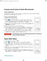
Frequency and Frequency Counter Measurements
Frequency Measurement
During AC/DC voltage or AC/DC current measurements, you can measure the signal
frequency by pressing
at any time.
Frequency Counter Measurement
1
Set the rotary switch to
.
2
Press
to select the frequency counter (
) function. The
default input signal frequency is divided by 1. This allows signals
up to a maximum frequency of 985 kHz to be measured.
3
Connect the red and black test leads to input terminals
V (red)
and
COM (black)
respectively.
4
Probe the test points and read the display.
5
If the reading is unstable or zero, press
to select division of
input signal frequency by 100 (
will be shown on the display).
This accommodates a higher frequency range of up to 20 MHz.
6
The signal is out of the U1253A frequency measurement range of
20 MHz if the reading is still unstable after
Step 5
.
Square Wave Output
1
Turn the rotary switch to
.
2
Press
to select duty cycle (%) on the primary display.
3
The default square wave frequency is 600 Hz as shown by the
secondary display, with a 50% duty cycle as shown by the primary
display.
4
Press
or
to scroll through the available frequencies (there are
28 frequencies to choose from).
5
Press
or
to adjust the duty cycle. The duty cycle can be set
from 0.390625% to 99.609375%, in steps of 0.390625%. The displayed
duty cycle has a resolution of 0.001%.
WA R N I N G
Use the frequency counter for low voltage applications. Never use the frequency
counter on AC power line systems.
U1253A QSG.fm Page 4 Tuesday, September 23, 2008 9:44 AM

