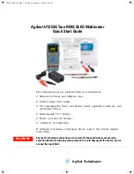
U1253A Quick Start Guide
Functions and Features
Input Terminals and Overload Protection
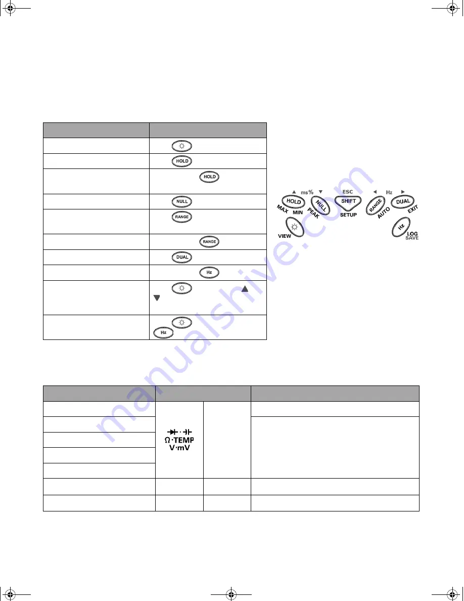
Action
Steps
Changes the OLED brightness
Press
.
Freezes the measured value
Press
.
Starts MIN|MAX|AVG|NOW
recording
Press and hold
for > 1 s.
Offsets the measured value
Press
.
Changes the measurement
range
Press
.
Turns on auto range
Press and hold
for > 1 s.
Turns on dual display
Press
.
Starts manual data logging
Press and hold
for > 1 s.
Views the logged data
Press
for > 1 s, press
or
to scroll through the logged
data.
Clears the logged data
Press
for > 1 s, press
for > 1 s.
Measurement Functions
Input Terminal
Overload Protection
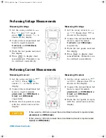
Voltage
COM
1000 Vrms
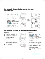
Diode
1000 Vrms
< 0.3 A short circuit current
Resistance
Capacitance
Temperature
Current (
μ
A and mA)
µA.mA
COM
440 mA/1000 V 30 kA/fast-acting fuse
Current (A)
A
COM
11 A/1000 V 30 kA/fast-acting fuse
U1253A QSG.fm Page 5 Tuesday, September 23, 2008 9:44 AM


