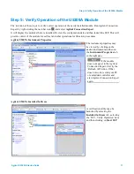
Step 5: Verify Operation of the U5309A Module
Perform a Verification of the U5309A (optional)
Requirements for Verification
The correct operation of the U5309A may be verified by the use of a simple application which carries out several
performance checks on a signal acquired from an external Function Generator.
Required Hardware
An external signal source is required. Almost any sine wave or function generator capable of generating a signal
with an amplitude of 300 mV rms into 50 Ω at a frequency of 1 MHz may be used.
Hardware
Description
Analog Signal Generator
e.g. Agilent N5181A, E4428C, ..
SMA cable
50 Ω Coaxial cable with SMA(m)
Operational Verification Procedure
Do not exceed the maximum voltage level at the INPUT connector (±3.4 V DC).
1. Configure the RF Generator to produce a Sine signal with a Frequency of 1.0 MHz, an Amplitude of
300 mV rms (+2.55 dBm).
2. Connect the Signal Generator output to the IN 1 connector, and turn on the output.
3. Launch the
Verify
utility from Agilent Connection Expert as explained in Step 5 of this Startup Guide. A
command shell window will open.
4.
Press any key
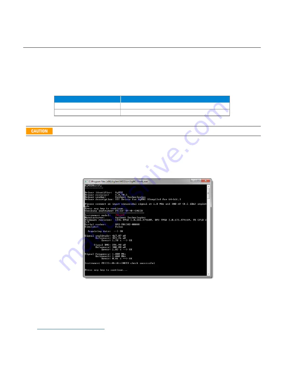
to start the test. The screen capture below shows the result of a successful verification:
If a Problem is Found
1. Verify that you have made all configuration settings as shown above.
2. Verify that the RF generator is ON and producing the desired signals at the end of the cable. This can be
done with an oscilloscope.
3. Verify that the problem is reproducible.
4. Contact Agilent technical support for assistance. Contact details may be found at:
www.agilent.com/find/contactus
18
U5309A Startup Guide

