background image

01-999124-00  J 0606

Dual and Dual Broadband NMR Probes Installation

19

Testing Probes on MERCURYplus

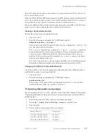
Successful operation depends on the existence of a probe calibration file for each probe 
that is used with the system

When the MERCURYplus NMR spectrometer is installed, the proper probe calibration files 
are set up, so that the system is ready to use when the installer leaves the site. Customers 
must update these files regularly to maintain optimal system performance
.

The probe calibration files must be created when the system is installed or the first time a 
probe is used. Create or change the probe calibration file as follows:

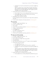
Creating a Probe Calibration File

Perform these steps for each probe that is tested.

1.

Log in as 

vnmr1

.

2.

Enter the following command in the VNMR input window:

addprobe(probe<,'system'>) 

where 

probe

 is a descriptive name for the probe (e.g., 

addprobe('id5mm')

 for 

an 5-mm indirect detection probe). 

The 

'system'

 keyword (e.g., 

addprobe('id400','system')

 makes the 

probe calibration files for this probe available to all users by placing the files in

/vnmr/probes

. Without the keyword, the files are placed in the 

vnmrsys


directory of the user entering the command (e.g., 

~vnmr1/vnmrsys/probes

and are only available to that user. 

The values for power, 

pw90

dmf

, and 

pp

 are initially set to 0 and filled in later by 

running the calibration procedures for the appropriate nuclei using GLIDE.

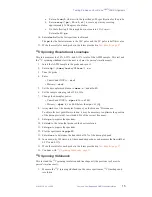
Changing to a Different Probe Calibration File

Use this procedure to switch to the appropriate calibration file when a different probe is 
installed after a probe is tested and calibrated,.

1.

Log in as 

vnmr1

.

2.

Enter the following command in the VNMR input window:

probe=probe_dir

Where probe_dir the name of the existing probe directory in 

/vnmr/probes


named for the new probe (e.g., 

probe='sw5mm'

).

1

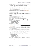
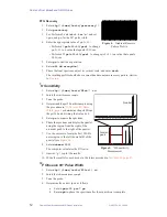
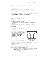
H Spinning Resolution & Lineshape 

This test measures the 0.11%, 0.55%, and 50% levels of the CHCl

3

 sample. This and the 

1

H spinning sidebands test (the next test) must be passed simultaneously and both tests 

plotted together.

1.

Insert the appropriate CHCl

3

 sample in the magnet and spin it.

2.

Enter 

rtp('/vnmr/tests/H1lshp')


nm


nt=1 vs=100 su

.

3.

Tune the probe.

4.

Enter a value for 

pw

 appropriate for your sample:

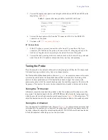
Sample (Part No.)

Value for pw

1% CHCl

3

, (00-968120-89)

90° pulse

5% CHCl

3

, (00-968120-99)

30° pulse

20% CHCl

3

, (00-968120-76)

20° pulse

Summary of Contents for VARIAN Dual

Page 1: ...tallation Varian Inc NMR Spectrometer Systems Pub No 01 999124 00 Rev J 0606 NOTICE This document contains references to Varian Please note that Varian Inc is now part of Agilent Technologies For more information go to www agilent com chem ...

Page 2: ...page 3 Connecting to VnmrS Systems page 3 Connecting to UNITY Series page 3 Connecting to MERCURY Series page 4 Tuning the Probe page 5 Returning to Normal Operation page 6 Tuning Ranges for Dual and Dual Broadband Probes page 6 Sample Tube Specification page 7 Testing Probes on VnmrS and UNITY INOVA Systems page 8 Testing Probes on MERCURYplus page 18 Test Results page 27 Pub No 01 999124 00 Rev ...

Page 3: ...00 200 PFG 54 5 1 H 13 C 01 911985 00 200 PFG 89 5 1H 13C 01 911988 00 200 PFG 54 5 1 H 19 F 15 N 31 P 01 910552 00 200 PFG 89 5 1 H 19 F 15 N 31 P 01 911991 00 200 54 5 1H 19F 15N 31P 01 902651 00 200 89 5 1H 19F 15N 31P 01 902654 00 300 89 5 1H 13C 01 910554 00 300 54 5 1 H 13 C 01 904510 01 300 PFG 89 5 1 H 13 C 01 911973 00 300 PFG 54 5 1H 13C 01 910556 00 300 PFG 89 5 1 H 19 F 15 N 31 P 01 91...

Page 4: ... and probe 5 Secure the probe flange to the magnet with the thumbscrews 6 Press the upper barrel down until it seats into the room temperature shim coil 7 Tighten the three set screws in the probe flange against the probe shield CAUTION Overtightening the set screws will dent the probe shield Connecting to VnmrS Systems 1 Connect the decoupler or proton port of the probe to the high band or proton...

Page 5: ...nector VT Control on the probe 6 Connect the VT nitrogen gas hose to the stub tee on the glass dewar projecting to the side at the base of the probe 7 Connect the body cooling air hose to the hose barb protruding from the bottom of the probe Connecting to MERCURY Series MERCURY Series includes the MERCURYplus MERCURY VxWorks Powered and the MERCURY systems Newer production MERCURYplus system have ...

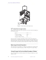
Page 6: ...rical counter system and probe label on the broadband channel that corresponds to the tuning of the nuclei to be decoupled observed The knurled tune knob changes the values on the numerical counter while the smooth knob operates the matching capacitor The lower the frequency of the nucleus the more the smooth match knob needs to be turned clockwise Tuning the 1 H Channel Alternately adjust the mat...

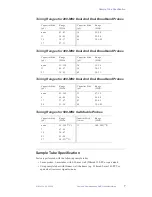
Page 7: ... the coil in the probe to resonance at the proton transmitter frequency The probe may need to be tuned after a sample or solvent is changed Returning to Normal Operation After tuning the probe enter dm n su to make sure the decoupler is not inadvertently left on Check the 1H channel tuning after X channel tuning and after a sample change Tuning Ranges for Dual and Dual Broadband Probes Ranges are ...

Page 8: ...528 PP or equivalent Using sample tubes with thinner wall thickness e g Wilmad 5 mm 545 PPT or equivalent increases signal to noise Capacitor Stick pF Range MHz Capacitor Stick pF Range MHz none 43 83 36 25 28 11 34 45 50 22 24 19 30 37 66 19 5 22 27 27 31 Capacitor Stick pF Range MHz Capacitor Stick pF Range MHz none 55 125 30 32 36 11 42 57 36 30 33 23 35 42 40 28 31 Capacitor Stick pF Range MHz...

Page 9: ...1 P Observe 90 Pulse Width page 13 31 P Sensitivity page 14 13C Observe 90 Pulse Width page 14 13 C Spinning Resolution Lineshape page 15 13 C Spinning Sidebands page 15 13C Sensitivity page 16 15 N Sensitivity page 17 Table 3 Acceptance Tests and Samples NMR Test Sample Part No 1 H PW90 1 H sensitivity 0 1 ethylbenzene 0 01 TMS 99 89 deuterochloroform CDCl3 00 968120 70 1 H spinning res lineshape...

Page 10: ...mand which calculates the γH2 for a given decoupler power level 8 Enter h2cal to calculate γH2 9 Record the result and use it during the 13 C 90 pulse width test 1 H Observe 90 Pulse Width 1 Install the 1 H quarter wavelength cable 2 Enter rtp vnmr tests H1sn su 3 Tune the probe on the ethylbenzene sample 4 Enter pw 5 at 1 lb 1 5 Obtain the spectrum and adjust the phase for a positive signal 6 Det...

Page 11: ... a value for pw appropriate for your sample 4 Enter ga to acquire the spectrum 5 Phase the spectrum and plot it using wp 250 6 Normalize the spectrum enter vs 10k and plot the expanded spectrum If floor vibration results in excessive noise around the base of the peak nt can be changed to a larger value e g nt 4 or nt 16 however if extreme vibrations are present it may be impossible to measure the ...

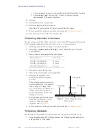
Page 12: ...he values of tpwr p1 and pw p1 1 H 90 and pw 2 p1 4 Enter profile 5 Enter the appropriate value for gzlvl1 Performa I gzlvl1 250 Performa II gzlvl1 4000 6 Enter ga and acquire a spectrum 7 Enter f full dc vsadj A peak about 16 kHz for Performa I or about 50 kHz for Performa II similar to Figure 3 is displayed 8 Use the cursors to find the width of this peak at 20 of the height 9 Enter setgcal to c...

Page 13: ...0 on this sample using the procedure in 1H Observe 90 Pulse Width page 9 or determine the pw90 from the pw360 and dividing that value by 4 5 Enter ga to acquire the spectrum 6 Phase the spectrum and display the quartet using the region from the right of the aromatic peak to the right of the quartet 7 Use the cursors to locate the best 200 Hz noise region to the left downfield of the quartet see Fi...

Page 14: ...uorotoluene sample 3 Tune the probe 4 Set the 19F 90 pulse width as determined in 19F Observe 90 Pulse Width page 12 5 Enter ga to acquire the spectrum 6 Enter dsnmax 200 The computer calculates the S N ratio 7 Answer y to plot the results 8 Write the results for each probe in the forms provided in Test Results page 27 31 P Observe 90 Pulse Width 1 Enter rtp vnmr tests P31sn su 2 Insert the triphe...

Page 15: ... C13sn su 2 Tune the probe 3 Change dpwr to 3 or 4 dB below the dpwr of γH2 4 Enter dm nny d1 10 ga 5 Array dof to set the decoupler frequency on the dioxane 1H resonance Optimize the position of the decoupler dof to within 0 4 Hz of the correct frequency to obtain the best possible resolution 6 Enter pw 5 ga 7 Adjust the phase for a positive signal 8 Expand the spectrum so that the signal is cent...

Page 16: ...nt 4 5 Set the decoupler modulation to dmm c and d1 60 6 Set the sample spinning rate at 20 5 Hz 7 Change the decoupler power VnmrS and INOVA dpwr to 30 to 42 dB Mercury dpwr to 3 or 4 dB below the dpwr of γH2 8 Array dof to set the decoupler frequency on the dioxane 1 H resonance To obtain the best possible resolution it may be necessary to optimize the position of the decoupler dof to within 0 4...

Page 17: ...tes between acquisitions to ensure that the C6D6 lines are fully relaxed 5 The signal of interest is the highest line of the C6D6 triplet see Figure 6 Use the cursors to select the best 1400 Hz noise region between the dioxane and benzene peaks 6 Enter dsnmax 1400 The computer calculates the S N ratio 7 Answer y to plot the results 8 Write the results for each probe in the forms provided in Test R...

Page 18: ...the probe b Enter array pw 20 r1 r1 to create a pw array covering approximately 360 degrees of nutation 9 When the last spectrum is obtained enter dssh The first null spectra is the 180 pulse therefore the 90 pulse width is one half the 180 pulse 15 N Sensitivity 1 Enter rtp vnmr tests N15sn nt 1 su 2 Tune the probe 3 Set the 15N 90 pulse width to the value determined in 15N Observe 90 Pulse Width...

Page 19: ...tion file by entering ACreport in the VNMR input window 4 Follow the instructions in Setting Up the Solvent Based Shim Files page 25 for configuring solvent based shims and the setlk macro for proper GLIDE and automation operation Probe Calibration Files Probe calibration files in vnmr probes contain pw90 tpwr dmf dpwr and pwx settings for each probe used with the system GLIDE automation and manua...

Page 20: ...he files in vnmr probes Without the keyword the files are placed in the vnmrsys directory of the user entering the command e g vnmr1 vnmrsys probes and are only available to that user The values for power pw90 dmf and pp are initially set to 0 and filled in later by running the calibration procedures for the appropriate nuclei using GLIDE Changing to a Different Probe Calibration File Use this pro...

Page 21: ...o see the difference in Hz between the cursors e Set th 11 the 0 11 level and repeat 7 Write the results for each probe in the forms provided in Test Results page 27 8 After the specifications are met do the following Write down the values for z0 lockpower and lockgain as they appear in the Acqi window Use the forms provided in Test Results page 27 Save the shims by entering in the VNMR input wind...

Page 22: ... of tof obtained in the proton spectrum 10 Repeat step 5 11 Write the results for each probe in the forms provided in Test Results page 27 1 H Observe 90 Pulse Width This procedure calibrates tpwr and the 90 pulse width for 1 H 1 Open GLIDE by clicking the GLIDE button in the VNMR menu 2 Click on the Setup icon 3 Insert the sample in the magnet using the Insert button in the Setup window 4 Select ...

Page 23: ...r each probe in the forms provided in Test Results page 27 31 P Observe 90 Pulse Width This procedure calibrates tpwr and the 90 pulse width for 31P 1 Make sure the appropriate quarter wavelength cable is installed 2 Open GLIDE by clicking the GLIDE button in the VNMR menu 3 Click on the Setup icon 4 Insert the sample in the magnet using the Insert button in the Setup window 5 Select Calibrate Pho...

Page 24: ...lotted 13 Write the results for each probe in the forms provided in Test Results page 27 1 H Sensitivity 1 Enter pw pw90 f full nm and skip to step 5 if the 90 pulse width calibration was just finished 2 Enter rtp vnmr tests H1sn su 3 Do the following after completing the 90 pulse width calibration using GLIDE getparam tpwr tpwr getparam pw90 pw 4 Tune the probe 5 Enter nt 1 ga to acquire and disp...

Page 25: ...pw pw90 f full nm and skip to step 5 3 Enter rtp vnmr tests P31sn su 4 If you completed the 90 pulse width calibration using GLIDE enter the following getparam tpwr tpwr getparam pw90 pw 5 Tune the probe 6 Enter ga to acquire the spectrum The spectrum is a single line 7 Set vp 0 and adjust vs so that the peak covers about half the screen 8 For noise measurement locate the cursor in a representativ...

Page 26: ... D2O and CD3OD The steps below describe how to save other solvent based shims and move the shim files to the vnmr shims directory You must still be logged in as vnmr1 Note that starting with VNMR 6 1 the names for shim files should be all lower case 1 Do the following for the primary solvent used Acetone CDCl3 and C6D6 as in the ATP skip to step 2 D2O or CD3OD or DMSO and it wasn t used in the ATP...

Page 27: ...2 To allow the system to automatically retrieve a set of shims for each solvent remove the double quotes around the following lines if e 0 5 or e1 0 5 then rts solv else exists userdir shims cdcl3 file e exists systemdir shims cdcl3 file e1 if e 0 5 or e1 0 5 then rts cdcl3 endif endif 3 Remove the quotes from the lines with the solvents you plan to use Replace the appropriate values of z0 lockpow...

Page 28: ... the probe or as specified by the contract 90 Pulse Width Resolution and Lineshape 50 0 55 0 11 1H Spinning Sidebands Sensitivity PFG Profile and Recovery if equipped with pfg Variable Temperature Range ____ to ____ C Probe Serial No Customer Initials System Frequency Nucleus Pulse width µs specification Results tpwr dpwr Notes 1H 19 F 31P 13 C γH2 Shim Set specify 1 H Spinning CHCl3 13 C Spinning...

Page 29: ...tract 90 Pulse Width Resolution and Lineshape 50 0 55 0 11 1H Spinning Sidebands Sensitivity Variable Temperature Range ____ to ____ C Probe Serial No Customer Initials System Frequency Nucleus Pulse width µs specification Results tpwr dpwr Notes 1 H 13 C γH2 Shim Set specify 1 H Spinning CHCl3 13 C Spinning ASTM Results Nucleus Specification Results Notes 1 H 13C Nucleus S N Results Notes 1 H 13 ...

Page 30: ...mrJ 2 1B parameter macro and command names Copyright 2006 Varian Inc 3120 Hansen Way Palo Alto California 94304 1 800 356 4437 http www varianinc com All rights reserved Printed in the United States The information in this document has been carefully checked and is believed to be entirely reliable However no responsibility is assumed for inaccuracies Statements in this document are not intended to...

Reviews: