background image


Chapter 6. NMR Room Layouts


50


Installation Planning Guide

01-999021-00  A0100

Summary of Contents for Varian MERCURY Series

Page 1: ...Powered MERCURY Series NMR Spectrometer Systems Pub No 01 999021 00 Rev A0100 NOTICE This document contains references to Varian Please note that Varian Inc is now part of Agilent Technologies For more information go to www agilent com chem ...

Page 2: ... characteristics of the software described in this manual may be changed at any time without notice Varian reserves the right to make changes in any products herein to improve reliability function or design Varian does not assume any liability arising out of the application or use of any product or circuit described herein neither does it convey any license under its patent rights nor the rights o...

Page 3: ...loor Vibration Requirements 17 2 8 Magnetic Environment 18 2 9 Radio Frequency Environment 19 2 10 Electrostatic Discharges 20 2 11 Ambient Temperature and Humidity 20 2 12 Ventilation 21 2 13 Helium and Nitrogen Refill Volumes and Intervals 21 Chapter 3 Site Preparation 23 3 1 Line Voltage Variation 23 3 2 Uninterrupted Power Supply UPS 24 3 3 Electrical Outlets 24 3 4 Compressed Air Supply 25 3 ...

Page 4: ...c Fields 35 5 1 Safety Hazards of Strong Magnetic Fields 35 5 2 Stray Field Plots 36 5 3 Posting Requirements for Magnetic Field Warning Signs 39 Chapter 6 NMR Room Layouts 41 6 1 RF Cable Harness 41 6 2 Magnetic Field Considerations 41 6 3 Typical Room Layouts 41 Index 51 ...

Page 5: ...gure 3 Platform Antivibration System Leg Placements and Sizes 16 Figure 4 Magnet Leg Antivibration System Leg Placement and Sizes 17 Figure 5 Stray Field Plots for 200 MHz Magnets 37 Figure 6 Stray Field Plots for 300 MHz Magnets 37 Figure 7 Stray Field Plots for 400 MHz Magnets 38 Figure 8 10 Gauss Warning Sign 40 Figure 9 5 Gauss Warning Sign 40 Figure 10 Magnet Area Danger Sign 40 ...

Page 6: ...d 18 Table 7 Spectrometer and Nuclei Operating Frequencies 19 Table 8 Ambient Temperature and Relative Humidity 20 Table 9 Liquid Helium Displacement for Room Ventilation Considerations 21 Table 10 Helium and Nitrogen Refill Intervals and Volumes 21 Table 11 Electrical Outlet Requirements 24 Table 12 Compressed Air Supply Source 25 Table 13 Air Conditioning Requirements 26 Table 14 Solaris Preinst...

Page 7: ... provides magnetic field safety data and shows stray field plots for each magnet system Chapter 6 NMR Room Layouts provides help in laying out the system room Safety Precautions Throughout this guide are important warnings and cautions that you should read and follow carefully These safety precautions have the following format and meaning WARNING Warnings are used when failure to observe instructi...

Page 8: ...nmark Herlev 42 84 6166 France Orsay 1 69 86 38 38 Germany Darmstadt 6151 70 30 Italy Milan 2 921351 Japan Tokyo 3 5232 1211 Korea Seoul 2 3452 2452 Mexico Mexico City 5 523 9465 Netherlands Houten 30 635 0909 Norway Oslo 9 86 74 70 Russian Federation Moscow 95 241 7014 Spain Madrid 91 472 7612 Sweden Solna 8 445 1601 Switzerland Zug 41 749 88 44 Taiwan Taipei 2 2698 9555 United Kingdom Walton on ...

Page 9: ... is usually provided Air Freight System is delivered to unloading dock or other easily accessible outside unloading point Factory to destination transit time is about two days not including time to clear customs Motor or Moving Van System is delivered to an easily accessible interior location or any interior location to which freight can be easily transported by movable dolly Excluded is transport...

Page 10: ...stallation Supplies on page 31 5 Make arrangements for workers and equipment to move the system upon delivery to the installation site Refer to 1 2 Moving the System After Delivery page 10 for details on moving the system Refer to 1 3 Selecting a Local Shipping Company page 11 for details on selecting a local shipping company 1 2 Moving the System After Delivery To avoid unnecessary expense be sur...

Page 11: ...e local shipping company uses a vehicle that will allow the magnet to be transported in an upright position for all transport methods that will be used See Table 1 and Table 2 for dimensions and weights of major system components Table 1 Magnet Dimensions and Weights as Shipped with Crate and Pallet Magnet type MHz mm Height cm in Width cm in Depth cm in Weight kg lb 200 54 135 53 79 31 89 35 132 ...

Page 12: ...f the damage report to the local Varian representative In case of damage the FOB block on the Varian Order Acknowledgment form determines owner responsibility FOB PALO ALTO Transfer of ownership occurs when the shipment leaves the factory The customer is responsible for claims for shipping damage Upon request Varian will provide assistance in filing claims FOB DESTINATION Transfer of ownership occ...

Page 13: ...c Environment page 18 2 9 Radio Frequency Environment page 19 2 10 Electrostatic Discharges page 20 2 11 Ambient Temperature and Humidity page 20 2 12 Ventilation page 21 2 13 Helium and Nitrogen Refill Volumes and Intervals page 21 Factors to consider when selecting the installation site include Accessibility to the delivery location Site size and ceiling height Floor rigidity and structural stre...

Page 14: ...nterference that may be present Each individual site must be analyzed to ensure optimum system performance Table 3 Magnet Dimensions and Weights with Stand and Legs Attached Magnet type MHz mm Height cm in Width cm in Depth cm in Operational Weight kg lb 200 54 183 72 76 30 66 26 136 300 200 54 LH235 228 90 78 31 78 31 315 693 200 54 LH365 235 92 5 78 31 78 31 362 796 300 54 183 72 69 27 69 27 152...

Page 15: ... 300 54 magnets or any magnet with both the sample changer and an antivibration system In these cases add 20 cm 8 in to the ceiling height requirements 2 3 Accessibility The site must also provide adequate access for the routine delivery of supply dewars containing liquid helium and nitrogen 2 4 Maximum Altitude The maximum altitude during operation is 2440 m 8000 ft The maximum during storage or ...

Page 16: ... Since the legs are hollow the actual surface contact with the floor is only 167 74 cm2 26 sq in total which creates relatively high point loading This is only a concern however if the floor covering is soft Magnet Weight Distribution With Antivibration System This section describes weight distribution for magnets installed with antivibration systems The weights of the magnets with stands and anti...

Page 17: ...provided in the manual MERCURY VX Accessory Installation this note is provided for information purposes only 2 7 Floor Vibration Requirements The floor must be sufficiently rigid to reduce the vibration from adjacent dynamic loads to a negligible level defined as no single peak vibration greater than 20 µg acceleration from 0 to 100 Hz For sites exceeding this specification antivibration equipment...

Page 18: ... elevators or forklift trucks Similar separation distances must also be maintained between the magnet and any object that can cause a detrimental effect on the field homogeneity or the structural integrity of the magnet Conditions that could interfere with the magnet include but are not limited to a wall with metal sheathing or steel studding a concrete support column with steel Objects that affec...

Page 19: ...er to determine the effect on a specific pacemaker Varian provides signs with each system to warn pacemaker wearers of this hazard Post the signs according to 5 3 Posting Requirements for Magnetic Field Warning Signs page 39 2 9 Radio Frequency Environment The site should be checked for radio frequency interference rfi at or near the operating frequencies of the spectrometer and most common nuclei...

Page 20: ...harge to the next object that is touched If this happens to be the system the system components can be damaged An overly dry atmosphere also tends to create an electrostatic charge As with any system based on integrated circuits the system is susceptible to static spikes both those generated on the power line and those generated in the lab area that must be suppressed 2 11 Ambient Temperature and ...

Page 21: ...um you get about 740 liters of helium gas 2 13 Helium and Nitrogen Refill Volumes and Intervals Table 10 lists typical refill volumes and intervals for helium and nitrogen Locating a reliable local source of liquid helium and nitrogen is particularly important Use the values listed in Table 10 when making arrangements for an on going supply of liquid helium and liquid nitrogen Table 9 Liquid Heliu...

Page 22: ...Chapter 2 Site Requirements 22 Installation Planning Guide 01 999021 00 A0100 ...

Page 23: ...ge do not exceed 8 of nominal line tap voltages 117 15 Vac Short term voltage variations sag or surge with a duration between several milliseconds and several seconds do not exceed 10 of nominal line tap voltage 117 15 Vac Line transients impulse with a duration between 1 µs and 800 µs not to exceed 50 V peak above or below nominal line tap voltage 117 15 Vac These transients must be measured at t...

Page 24: ... least one step down transformer To minimize ground loop interference these outlets should all be on the same 20 A service It is strongly recommended that surge protection be provided MERCURY VX NMR Console requires a dedicated single phase continuous duty 117 15 Vac 50 60 Hz power line The basic system draws less than 1 kW for 117 Vac so a 15 A circuit is adequate Terminate the line within 2 7 m ...

Page 25: ...upplied filter assembly and air hose to the magnet The filter assembly includes a 0 to 400 kPa 0 to 100 psi pressure gauge a reduction valve a standard 20 micron air filter and a coalescing oil filter 99 9 percent oil removal efficiency The maximum input to the reducer is 100 psi 690 kPa 7 kg cm2 In areas where humidity is high or where moisture in the air supply is a problem a prefilter with an a...

Page 26: ...an be answered in real time by Varian s NMR applications people As a matter of policy Varian provides online support during installation and during the warranty period If direct access to the internet is not technically feasible a high quality analog telephone line can be used Varian will provide a high speed modem during the system installation If internal security policies preclude ready modem o...

Page 27: ...an be present with a minimum total disk space of 1 gigabyte GB Graphics can be plain or the GX version the GX version provides higher performance Graphics higher than GX i e GXplus GS GT are not supported by Varian software Varian has not performed a full evaluation of higher lever graphics boards and cannot guarantee complete compatibility Purchasing Software Media Sun computers whether purchased...

Page 28: ... for VNMR operation In this case only a copy of the Solaris media is not required Guidelines but not step by step instructions are contained in the VNMR and Solaris Software Installation Manual for the case of a two disk system Varian installers are not trained to perform these operations If you have purchased the Sun computer from Varian you must have a copy of the Solaris CD ROM available for th...

Page 29: ... the following server standalone or dataless client A server is a system that provides network services such as file transfer and storage space A standalone system is a system that contains its own hard disk and bootup files A dataless client sometimes called diskless client is a system without its own hard disk and uses an NFS server for the operating system storage and other services For the pur...

Page 30: ...te the use of back quotes in this command Selecting a Subnet Mask The subnet mask is a number that is used to split IP addresses into the network Internet and host parts If your site does not use multiple subnets use the default number otherwise consult your network administrator For a computer connected to a network the command cat etc netmasks can be used Selecting the Name Service Type The name...

Page 31: ...quid nitrogen supply Helium gas supply Nitrogen gas supply Face mask and thermal gloves Heat gun Non magnetic ladder Locating a reliable local source of liquid helium and nitrogen is particularly important As soon as possible after ordering a system make arrangements for an initial delivery and an on going supply of liquid helium and nitrogen Electrical Power Strip and Surge Protector A six outlet...

Page 32: ... MHz and 300 MHz magnets use a rigid transfer tube that must be inserted into the storage dewar and magnet dewar simultaneously without bending For that reason we recommend the 100 L dewar When ordering liquid helium be sure that the supply dewar has a diameter less than 70 cm 27 5 in The 400 MHz and long hold magnets uses a flexible transfer tube that inserts into most sizes of supply dewars Liqu...

Page 33: ...chemically pure with a flow rate through the pressure of 19 LPM 40 SCFH at 207 kPa 30 psig For low temperature operation use prepurified grade gas 99 99 85 C dew point CAUTION To avoid movement caused by magnetic field attraction helium gas and nitrogen gas cylinders made of magnetic material must be kept outside the 5 gauss limit of the magnet and firmly secured Face Mask and Thermal Gloves If cr...

Page 34: ...tallation Supplies and Equipment In addition to the required supplies and equipment the following items are recommended Cryogenic equipment rack Monitor degaussing coil Details about each item are presented in the following sections Cryogenic Equipment Rack Various items are used around the magnet for routine maintenance and handling These include helium transfer tube flutter tube Tygon tubing sti...

Page 35: ...warning of magnetic field hazards Refer to Posting Requirements for Magnetic Field Warning Signs on page 39 for an explanation of the types of signs and the sign posting requirements Additional signs are available from Varian at no charge Because the magnetic field exists both horizontally and vertically the effect of the field on persons electronic equipment computers and other objects located ab...

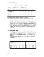
Page 36: ...from the magnet centerline CL The values are typical but may vary between individual magnets Gauss levels should be checked after a particular magnet has been installed The magnet system stray field values in Table 19 were provided by Oxford technical documentation Table 18 Stray Field Data for Oxford Magnets Magnet Type Radial Distance cm Axial Distance cm MHz mm 0 6 kG 6 kG 20 kG 0 6 kG 6 kG 20 ...

Page 37: ...1 5 0 5 1 5 Axial distance from magnet CL m Radial distance from magnet CL m 1 75 1 50 5 1 45 1 20 10 0 90 1 05 25 field values in gauss Figure 6 Stray Field Plots for 300 MHz Magnets standard and long hold 1 0 2 0 2 0 1 0 300 54 magnet 0 5 1 5 0 5 1 5 Axial distance from magnet CL m Radial distance from magnet CL m 2 20 1 70 1 75 1 30 0 97 1 26 5 10 25 field values in gauss ...

Page 38: ...1 999021 00 A0100 Figure 7 Stray Field Plots for 400 MHz Magnets 1 0 2 0 2 0 1 0 0 5 1 5 0 5 1 5 Axial distance from magnet CL m Radial distance from magnet CL m 2 80 2 20 2 24 1 76 1 29 1 65 2 5 2 5 5 10 25 field values in gauss 400 54 magnet standard and long hold ...

Page 39: ...to the IEEE ANSI C95 1 1991 standard For further information refer to the RF Environment section of the Installation Planning Guide Warning Signs Varian provides signs to help customers meet this posting responsibility These signs must be posted according to the following requirements before the magnet is energized 1 10 gauss warning signs Figure 8 Post along the 10 gauss perimeter of the magnet s...

Page 40: ...ious injury or death to persons with implanted or attached medical devices such as pacemakers and prosthetic parts Such persons must not go closer to the magnet than this sign until safety at a closer distance is identified by a physician or device Magnetic Media ATM Credit Cards Strong magnetic fields are present that can erase magnetic media disable ATM and credit cards and damage some watches D...

Page 41: ...ields on page 35 for stray magnetic field plots 6 3 Typical Room Layouts In the room layout illustrations the dotted circles around the magnets represents the possible radial extent of the 5 gauss stray field In the room layouts with the optional SMS autosampler the location of the autosampler depends on the orientation of the magnet Note that long hold magnets are the same size as the 400 54 cryo...

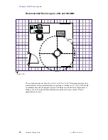
Page 42: ... Size 200 and 300 MHz Room dimensions are about 2 6 m 2 9 m 8 5 ft 9 5 ft A distance of 1 7 m 5 3 4 ft should be maintained around the magnet to prevent interference with electronic components A distance of 1 m 3 ft should be maintained around the standard cabinet If space permits the alternate arrangements shown in the following sections of this chapter are recommended Drawn approximately to scal...

Page 43: ... m 10 ft 14 ft This arrangement provides comfortable access for operator and service personnel A distance of 1 7 m 5 3 4 ft should be maintained around the magnet to prevent interference with electronic components A distance of 1 m 3 ft should be maintained around the standard cabinet Drawn approximately to scale MERCURY Cabinet 5 gauss line 1 4 in 1ft ...

Page 44: ... m 14 ft 14 ft This arrangement provides comfortable access for operator and service personnel A distance of 1 7 m 5 3 4 ft should be maintained around the magnet to prevent interference with electronic components A distance of 1 m 3 ft should be maintained around the electronics cabinet Drawn approximately to scale MERCURY Cabinet 5 gauss line 1 4 in 1ft ...

Page 45: ...ce with electronic components A distance of 1 m 3 ft should be maintained around the cabinets The table on which the SMS autosampler sits is 1 m 1 m 3 ft 3 ft Drawn approximately to scale The SMS autosampler is about 79 cm 79 cm 36 in 36 in The following illustrations show the preferred orientation of the SMS table to the magnet Refer to the Sample Management Systems manual for details about sampl...

Page 46: ... about 4 4 m 4 6 m 14 5 ft 15 2 ft The magnet is 80 cm 32 in in diameter A minimum of 3 m 10 ft should be maintained around the magnet to prevent interference with electronic components A distance of 1 m 3 ft should be maintained around the standard cabinet Drawn approximately to scale MERCURY Cabinet 400 54 5 gauss line 1 4 in 1ft ...

Page 47: ...nterference with electronic components A distance of 1 m 3 ft should be maintained around the standard cabinet The table on which the SMS autosampler sits is 1 m 1 m 3 ft 3 ft Drawn approximately to scale The SMS autosampler is about 79 cm 79 cm 36 in 36 in The following illustrations show the preferred orientation of the SMS table to the magnet Refer to the Sample Management Systems manual for de...

Page 48: ...lation Planning Guide 01 999021 00 A0100 MERCURY VX Illustrations for Room Layout MERCURY Cabinet MERCURY Cabinet SMS autosampler and table SMS autosampler and table 200 300 long hold 400 54 5 gauss line 5 gauss line 200 or 300 1 4 in 1ft ...

Page 49: ...6 3 Typical Room Layouts 01 999021 00 A0100 Installation Planning Guide 49 Blank Grid for Room Layout 1 4 in 1ft ...

Page 50: ...Chapter 6 NMR Room Layouts 50 Installation Planning Guide 01 999021 00 A0100 ...

Page 51: ...console to magnet 41 documentation 28 domain name 30 domainname command 30 E electrical outlet requirements 24 accessories 24 host computer and peripherals 24 test equipment 24 electrical outlets 24 electrical power surge protector 31 electrostatic discharge 20 antistatic spray 20 carpeting requirements 20 caution 20 floor coverings 20 grounding 20 preventing 20 electrostatic discharges 20 elevato...

Page 52: ...rogen refill volumes 21 NPT fitting 25 O on line documentation 28 opening crates 12 Order Acknowledgment form 10 12 P pacemaker hazard 35 postdelivery instructions 12 posting requirements 39 power conditioning system 23 power line analyzer 23 power outages frequent and short 24 power stick 15 power supplies uninterrupted 24 predelivery checklist 10 pregnancy hazard 35 preinstallation worksheet 29 ...

Page 53: ...ndicator 10 11 tip and tell indicators 11 transfer of ownership 12 transfer tube 15 32 34 U uname n command 30 UPS systems 24 V van delivery 9 Varian Order Acknowledgment form 9 Varian sales and service centers 8 ventilation 21 vertical magnetic fields 35 vibration requirements 17 voltage variations 23 VT accessory 32 33 W warning signs 35 39 warnings defined 7 weight distribution for magnets 16 Y...

Reviews: