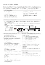
Users can identify the status of chassis body through the voltmeter, the beeper and lights mounted on HUNTER 2.0. For details, please
refer to Table 2.1.
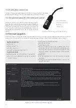
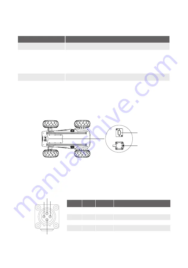
HUNTER 2.0 provides two 4-pin aviation connectors and one DB9 (RS232) connector. (The current version can be used for upgrade of
firmware but do not support for command).The position of the top aviation connector and DB9 interface is shown in Figure 2.3.
HUNTER 2.0 has each aviation extension interface respectively on top and at rear end which is configured with a set of power supply and
a set of CAN communication interface. These interfaces can be used to supply power to extended devices and establish communication.
The specific definitions of pins are shown in Figure 2.4.
It should be noted that, the extended power supply here is internally controlled, which means the power supply will be actively cut off
once the battery voltage drops below the pre-specified threshold voltage. Therefore, users need to notice that HUNTER 2.0 platform will
send a low voltage alarm before the threshold voltage is reached and also pay attention to battery recharging during use.
2.1 Status indication
2.2 Instructions on electrical interfaces
Voltage
Replace battery
Robot powered on
The current battery voltage can be read from the voltmeter on the rear electrical panel.
Rear lights are switched on.
When the battery voltage is lower than 24.5V (if the BMS is connected, the SOC is judged to be lower
than 15%) , the chassis body will give a beep-beep-beep sound as a warning. When the battery
voltage is detected as lower than 24V(if the BMS is connected, the SOC is judged to be lower than
10%), HUNTER 2.0 will actively cut off the power supply to external extensions and drive to prevent
the battery from being damaged. In this case, the chassis will not enable movement control and
accept external command control.
Status
Description
Table 2.1 Descriptions of Chassis Status
Figure 2.3 Schematic Diagram of HUNTER 2.0 Electrical Interface on Top
2.2.1 Top electrical interface
DB9 interface
External interface
Figure 2.3 Description of Top Aviation Interface Pins
2
1
4
3
1
2
3
4
Power
CAN
Power
CAN
VCC
GND
CAN_H
CAN_L
Power positive, voltage range 21-26.8V, singly maximum
current 10 A, total current is less than 15A
Power negative
CAN bus high
CAN bus low
Pin No.
Pin Type
Function and
Definition
Remarks
3


