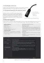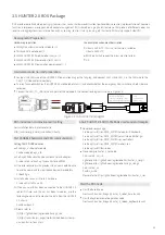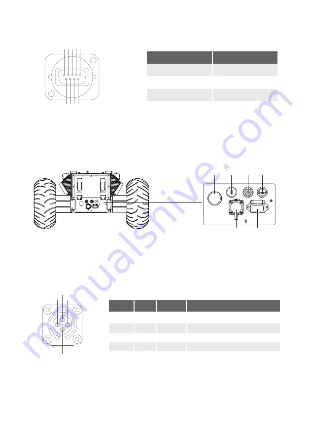
The extension interface at rear end is shown in Figure 2.6, where Q1 is the power display; Q2 is the switch of manual parking release; Q3 is
the power switch; Q4 is the buzzer; Q5 is CAN and 24V power extension interface; Q6 is charging interface.
Specific definitions for pins of Q5 are shown in Figure 2.7. The rear panel provides the same CAN communication interface and 24V power
interface with the top one (two of them are internally inter-connected). The pin definitions are given in Figure 2.7.
2.2.2 Rear electrical interface
Figure 2.6 Rear View
Figure 2.5 Description of Top DB9 interface
Figure 2.7 Description of Rear Aviation Interface Pins
Pin No.
2
3
5
Definition
RS232-RX
RS232-TX
GND
2
1
4
3
1
6
7
8
9
2
3
4
5
1
2
3
4
Power
CAN
Power
CAN
VCC
GND
CAN_H
CAN_L
Power positive, voltage range 21-26.8V, single maximum
current 10 A, total current is less than 15A
Power negative
CAN bus high
CAN bus low
Pin No.
Pin Type
Function and
Definition
Remarks
4
Q1
Q2
Q3
Q4
Q5
Q6
Top DB9 expansion interface pin definition.


