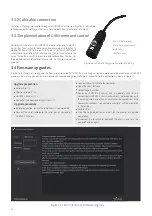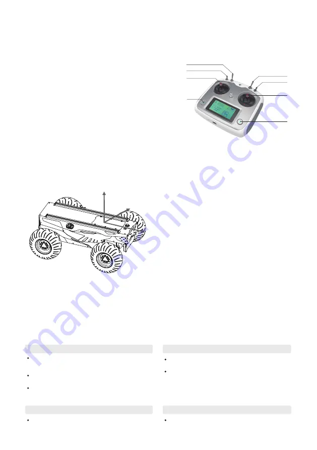
FS RC transmitter is provided (optional) for HUNTER 2.0. In this product, we use the left-hand-throttle design. Refer to Figure 2.8 for its
definition and function.
This section introduces the basic operation and development of the HUNTER 2.0 platform using the CAN bus
interface.
The function of the button is defined as: SWC and SWD are
temporarily disabled. Among which SWA is the parking switch
lever, turn to the top to release the parking mode, turn to
bottom is the parking mode. (The remote control can be
performed normally after the parking mode is released.) SWB
for control mode selection, top position for command control
and the middle position for remote control mode; S1 is the
throttle button, which controls the forward and backward of
HUNTER 2.0; S2 controls the steering of the front wheels, and
POWER is the power button, press and hold it to turn on.
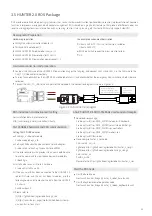
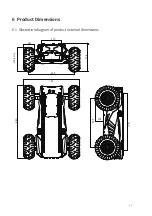
As shown in Figure 2.9, the chassis body of HUNTER 2.0 is in parallel with X
axis of the established reference coordinate system. In the remote control
mode, push the remote control stick S1 forward to move in the positive X
direction, push S1 backward to move in the negative X direction. When S1
is pushed to the maximum value, the movement speed in the positive X
direction is the maximum, When pushed S1 to the minimum, the
movement speed in the negative direction of the X direction is the
maximum; the remote control stick S2 controls the steering of the front
wheels of the car body, push S2 to the left, and the chassis turns to the left,
pushing it to the maximum, and the steering angle is the largest, S2 Push
to the right, the car will turn to the right, and push it to the maximum, at
this time the right steering angle is the largest. In the control command
mode, the positive value of the linear velocity means movement in the
positive direction of the X axis, and the negative value of the linear velocity
means movement in the negative direction of the X axis; the steering angle
is the steering angle of the inner wheel.
A reference coordinate system can be defined and fixed on the chassis body as shown in Figure 2.9 in accordance with ISO 8855.
2.4 Instructions on control demands and movements
2.3 Remote control instructions
Figure 2.8 Schematic Diagram of Buttons on FS RC transmitter
SWC
SWD
S2
SWB
SWA
S1
POWER
POWER
3 Getting Started
3.1 Use and operation
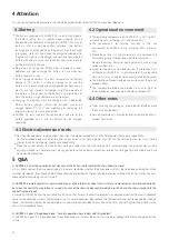
The basic operating procedure of startup is shown as follows:
Check
Shutdown
Emergency stop
Startup
Check the condition of HUNTER 2.0. Check whether there are
significant anomalies; if so, please contact the after-sale service
personal for support;
Check the state of emergency-stop switches. Make sure both
emergency stop buttons are released;
For first-time use, check whether Q3 (drive power supply switch)
on the rear panel has been pressed down; if so, please release it,
and then the drive will be powered off.
Press the button Q3 to cut off the power supply.
Press down emergency push button on the top of HUNTER 2.0
chassis body.
Press Q3 button, and normally, the voltmeter will display correct
battery voltage and front and rear lights will be both switched on;
Check the battery voltage, the normally voltage range is 24~26.8V,
if there is continuous “beep-beep-beep...” sound from beeper,it
means the battery voltage is low, please charge the battery.
5
Figure 2.9 Schematic Diagram of Reference Coordinate System for Chassis Body
Z
Y
X


