AgileX Robotics (Dongguan) Co.,Ltd.
22
}
return
checksum
;
}
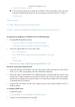
Figure 3.1 CAN Message Check Algorithm
3.3.2 CAN cable connection
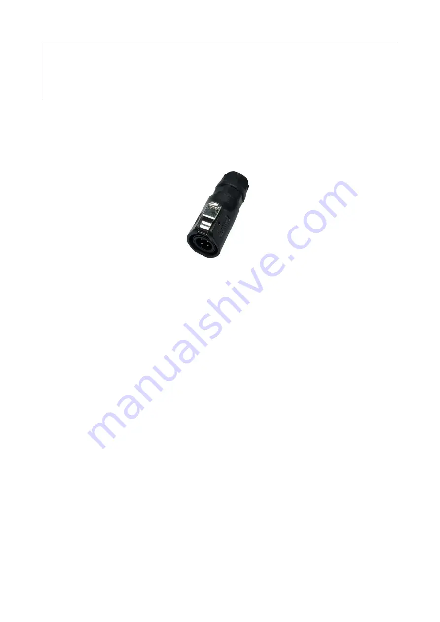
2 aviation male plugs are supplied along with SCOUT 2.0 as shown in Figure 3.2. Users need to lead
wires out by welding on their own. For wire definitions, please refer to Table 2.2.
Figure 3.2 Schematic Diagram of Aviation Male Plug
Note: In the current SCOUT 2.0 version, only the top interface is open to external extension.
The maximum achievable output current is typically around 5 A.
3.3.3 Implementation of CAN command control
Correctly start the chassis of SCOUT 2.0 mobile robot, and turn on DJI RC transmitter. Then, switch
to the command control mode, i.e. toggling S1 mode of DJI RC transmitter to the top. At this point,
SCOUT 2.0 chassis will accept the command from CAN interface, and the host can also parse the
current state of chassis with the real-time data fed back from CAN bus. For the detailed content of
protocol, please refer to CAN communication protocol.
3.4 Communication using RS232
3.4.1 Introduction to serial protocol
This is a serial communication standard which was formulated collectively by Electronic Industries
Association (EIA) together with Bell System, modem manufacturers and computer terminal
manufacturers in 1970. Its full name is called "the technical standard for serial binary data exchange
interface between data terminal equipment (DTE) and data communication equipment (DCE). This
standard requires to use a 25-pin DB-25 connector of which each pin is specified with corresponding
signal content and various signal levels. Afterwards, RS232 is simplified as DB-9 connector in IBM
PCs, which has become a de facto standard since then. Generally, RS-232 ports for industrial control
only use 3 kinds of cables - RXD, TXD and GND.


