AgileX robotics (Dongguan) Co., Ltd.
6
/
27
Users can identify the status of vehicle body through the voltmeter, the power supply and lights
mounted on SCOUT MINI.
Tail power switch: When the power switch is pressed, the ring indicator light will enter constant
mode.
Power indication: the tail power display module showing the information of the power capacity
and voltage of the current battery.
Front light: Front width light, can be switched by RC transmitter and command.
2.2 Instructions on electrical interfaces
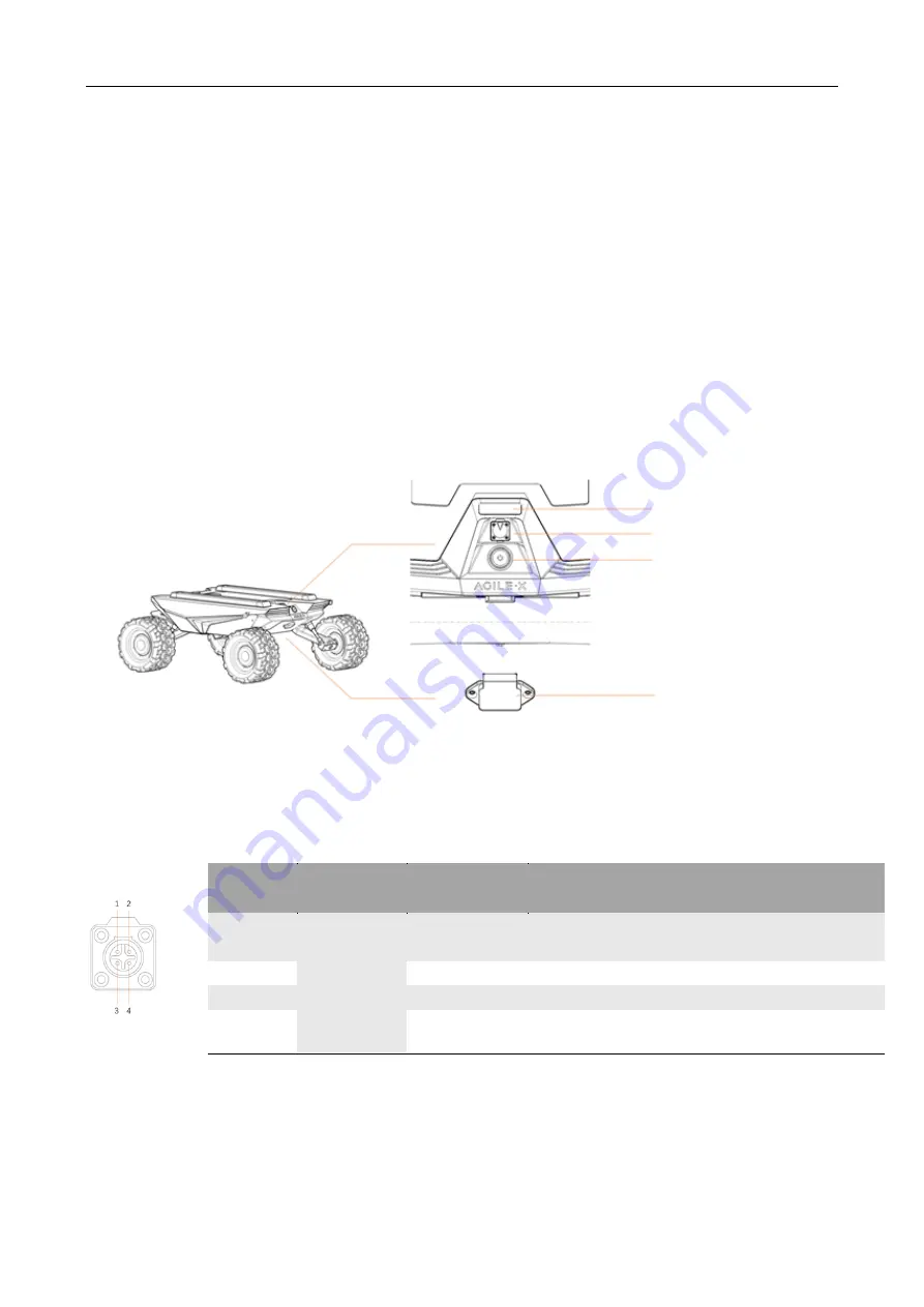
In the SCOUT MINI tail minimalist design, all electrical interfaces are in the tail. The interfaces
include voltage display interactive module, extension interface, power switch and charging interface.
The position of each module at the tail is as shown in the figure.
SCOUT MINI aviation extension interface is configured with both a set of power supplies and a set
of CAN communication interfaces. These interfaces can be used to supply power to extended
devices and establish communication. The specific definitions of pins are shown in Figure 2.4.
Pin No.
Pin Type
Function and
Definition
Remarks
1
Power
VCC
Power positive, voltage range 23 - 29.2V, MAX.
current 5A
2
GND
Power negative
3
CAN
CAN_H
CAN bus high
4
CAN_L
CAN bus low
2.3 Remote control instructions
FS RC transmitter is an optional feature of SCOUT MINI for users to choose as actually required.
With this RC transmitter designed on the left throttle in this product, users can easily control
SCOUT MINI universal robot chassis. Its definitions and functions are shown in Figure 2.9 for
Voltmeter
Extension interface
Power switch
Charging interface


