27
Above Ground Set-up
1.
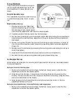
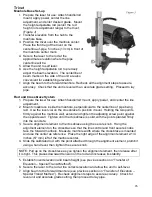
Prepare laser for use: mount the sighting scope
and attach to a 5/8”-11 tripod. If a dome head
tripod is used the laser may be attached directly;
to attach to a flat head tripod, use the adaptor.
Center the line adjustment, and set grade at
exactly zero.
2.
Measure over from an offset hub and position
the tripod directly over the pipe centerline trying
to keep the top of the tripod as level as possible.
Use a plumb bob if needed. Spread the tripod
legs and plant them firmly into the ground to
provide a stable base.
3.
Allow the laser to self-level.
4.
Slightly loosen the tripod securing knob and turn
the laser and scope to the rod held at the
manhole hub. Tighten the knob, then use the
line adjust buttons to align the beam exactly to
the rod. Take a reading (sometimes called
“back-sight” elevation) at the beam centerline. This measurement plus the “cut” at that
hub will be the HI (Instrument Height) above the invert.
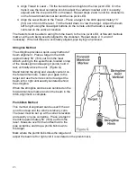
If the grade pole is used on top of the pipe, allow for the height difference when setting
up (Figure K). Set the centerline of the above ground target at the correct distance to
the invert OR to the top of the pipe.
5.
Enter the desired percent grade.
6.
Loosen the tripod securing knob, roughly aim the laser to the forward marker at the
next manhole and tighten. Depending on the package used, use the red filter sighting
scope to find the beam on a target at the forward marker and use the line adjust
buttons to get to centerline, or if using the remote control, walk the beam to the
forward marker and use the remote to put the beam on the centerline.
7.
Enter the desired grade on the unit and lay pipe.
Calculating Percent of Grade
Grade is the amount of slope over a specific distance and usually is expressed as percent of
grade, the rise or fall per 100 ft. For example, a 5 ft rise over a distance of 100 ft 5%
grade.
% Grade =
RISE(+) or FALL(-)
DISTANCE
X 100
Ensure that the Distance and Rise or Fall measurements are in the same units. For example,
if the Distance is in feet, the Rise or Fall must be measured in feet.
Summary of Contents for GradeLight 3000
Page 1: ...GradeLight 3000 Pipe Laser ...
Page 4: ...3 Laser Overview ...
Page 38: ...37 ...
Page 39: ...38 ...
Page 40: ...39 Printed in USA AM1145 3 10 Specifications subject to change without notice ...


