STAGE 84
THE MAIN CIRCUIT BOARD
01
. FIXING THE FORWARD SUPERSTRUCTURE
84-01
84-02
PB
84-02
11-03
11-04
11-02
11-04
11-02
11-04
01
02
Note 1:
Be extremely careful when fixing the
superstructure (steps 6 to 8 on page 16). In order to avoid
damaging the model, it is advisable to ask someone to help
you. They can hold the superstructure firmly in place while
you fit the 6 screws into the upper deck from below.
Note 2:
In the assembly instructions, we have used the
names on the cable labels, rather than the part numbers.
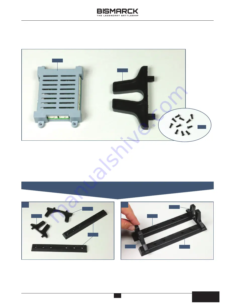
COMPONENTS CHECKLIST
84-01:
Main circuit board
84-02
: Hull support
PB:
Eleven 2 x 5mm PB screws
Take the two support stands assembled in stage 11.
Remove the hull supports
11-02
and
11-03
from the
bases
11-04
, as shown in the photo.
Position the two bases
11-04
side by side and spaced
apart, as shown. Fit the pegs on the hull supports
11-02
and
84-02
into the sockets at each end of the
bases
11-04
, to make a temporary support stand.
15
15
AGORA
MODELS
PB
AGORA
MODELS


