STAGE 91
THE AFT FIRE CONTROL POST
01
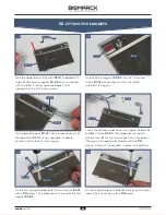
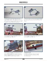
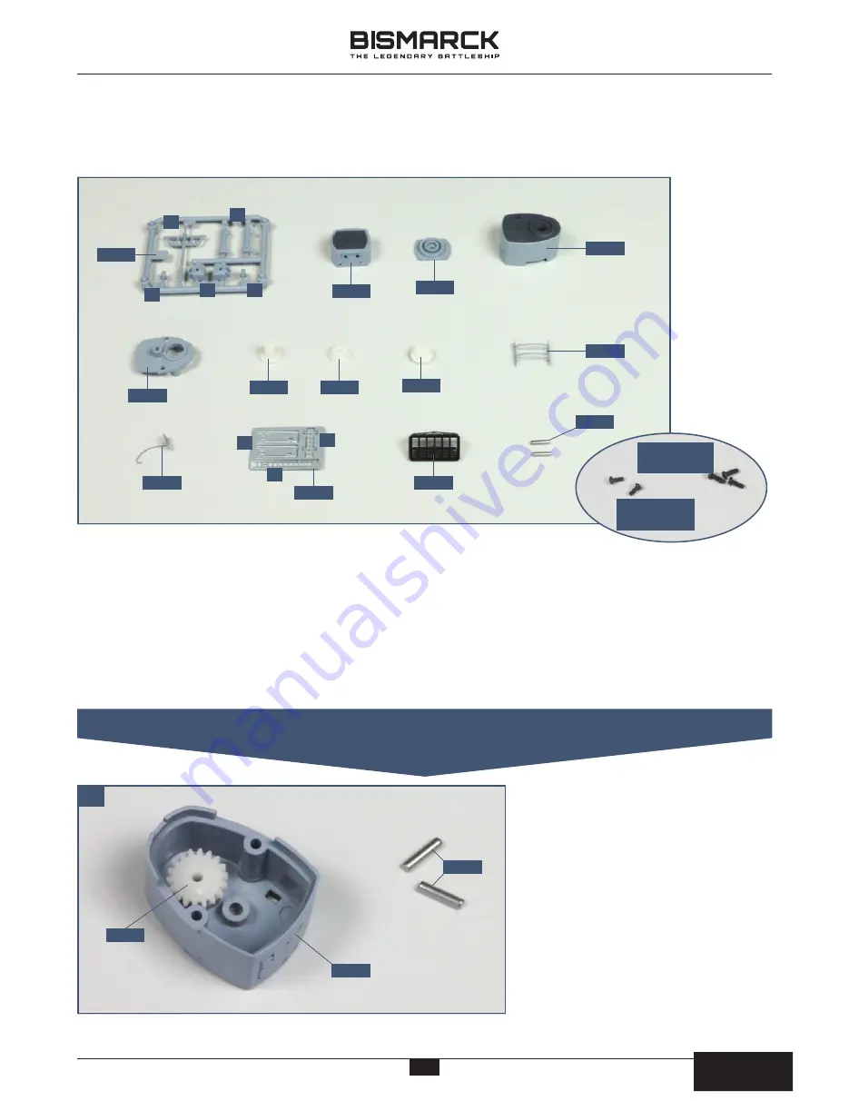
. FITTING THE MOTOR IN THE AFT CONTROL POST
B
C
A
91-04
91-02
D
C
4
PB
2 x 5mm
PB
1.7 x 4mm
91-03
91-05
91-06
91-07
91-08
91-09
91-10
91-11
91-12
91-13
F
E
G
91-01
01
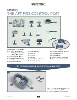
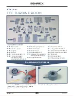
COMPONENTS CHECKLIST
91-01:
Small parts for the
rotating dome and the
control post (A to D)
91-02
: Aft rotating dome
91-03:
Base of the rotating
dome
91-04:
Aft control post
91-05:
Base plate
91-06:
Cog
91-07:
Cog
91-08:
Cog
91-09:
Ladders with rails
91-10:
Cooling coil
91-11:
Rails and ladders (E to G)
91-12
: Radar antenna
91-13:
Two shafts
PB:
Three 2 x 5mm PB screws
PB:
Two 1.7 x 4mm PB screws
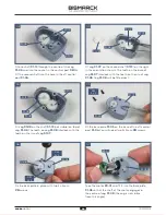
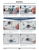
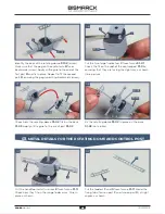
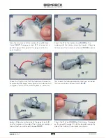
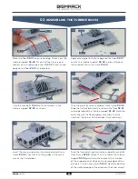
Place the aft control post
91-04
on your
worktop and fit the cog
91-06
in place
as shown. Have two shafts
91-13
ready.
91-04
91-06
91-13
43
43
AGORA
MODELS
PB
AGORA
MODELS


