STEP 4
STEP 5
3
4
1
2
3
5
1
6
4
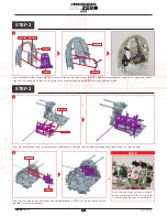
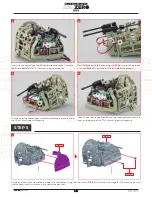
Glue the three tabs on the right side frame assembled in stage 24 to the three notches on the cockpit floor, and glue the two lugs on
the instrument panel into the two holes on the right side frame.
Align and glue the holes in the cockpit partition assembled in STEP 2 to the two protrusions on each of the left and right side frames. A
little extra glue can be applied to adjoining surfaces in 1–4 . Our video series shows you how and demonstrates the gluing technique.
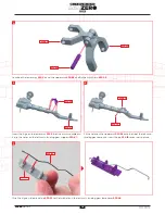
Fix the partition wall assembled in stage 19 to the cockpit using the two screws
019-03
that came with stage 19. The machine guns fit
into the semi-circular notches at the top of the partition.
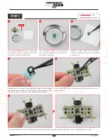
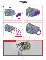
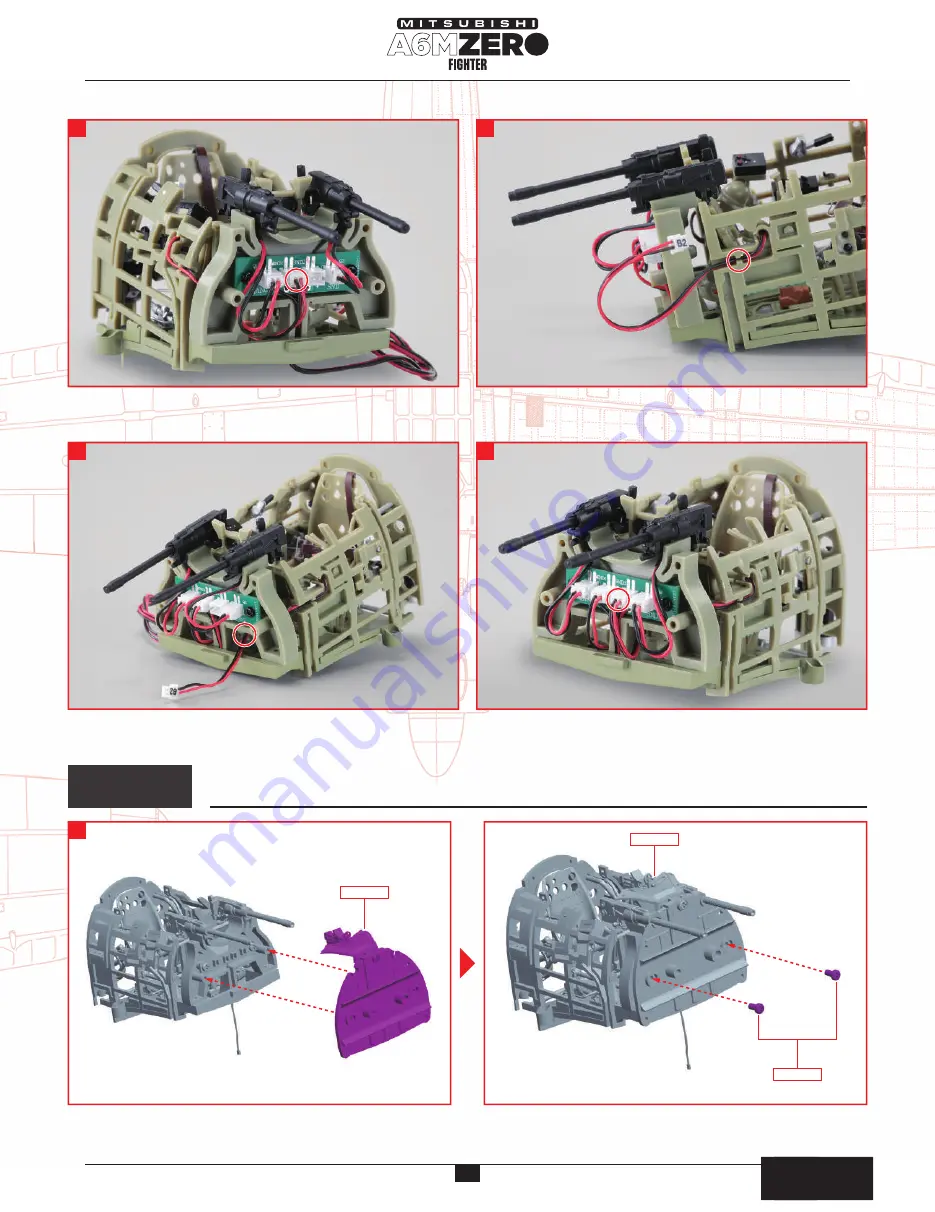
Pass the cord of the cockpit interior light
023-04
on the right
side of the cockpit through the groove on the outside of the
frame on the right side of the cockpit.
Pull the tip of the cockpit-light wire forward through the hole under
the 7.7mm machine gun magazine.
Insert the connector labelled B1 into the second socket from the
left on the board of the 7.7mm machine gun magazine.
Pull the tip of the cockpit-light wire forward through the hole under
the 7.7mm machine gun magazine.
Insert the connector labeled B2 into the second socket from the
right on the board of the 7.7mm machine gun magazine.
Pass the wire of the left interior light
025-04
through the groove
on the outside of the frame on the left side of the cockpit.
022-01
019-01
019-01
026-02
019-03
組み立てガイド
組み立てガイド
7
AGORA
MODELS


