S E T T I N G T H E C H A M F E R H E I G H T
-
DISCONNECT TOOL FROM POWER SOURCE.
1.
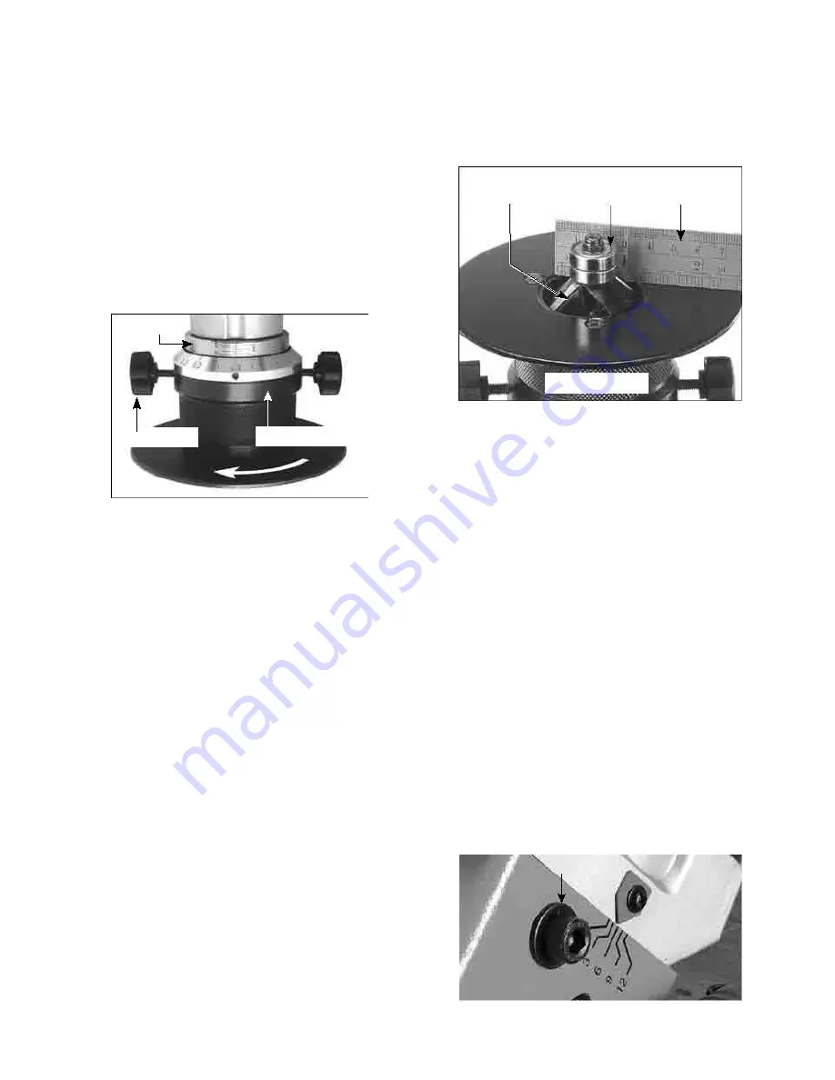
Loosen the 2 lock knobs
2.
Referring to the fixed dial scale and
the dial ring on the support deck, turn
the entire support deck assembly to set
the chamfer height as desired.
3.
retighten the 2 lock
knobs. Dial scale
Lock knobs
Support deck
ZEROING-IN THE CHAMFER HEIGHT-
DISCONNECT TOOL FROM POWER SOURCE.
Note: The machine’s chamfer height is set
at zero from the factory. If the setting is
disturbed, it must be zeroed in. Follow the
instructions below for zeroing-in.
1.
Loosen the 2 lock knobs then loosen
the support deck assembly so that the
inserts are below flush level.
2.
Use a steel ruler or other accurate
device with a right angle . While
keeping the ruler square with the
impeller and the support deck, slowly
adjust the support deck until the ruler
just touches the carbide insert. This is
the zero point.
3.
Once the zero point is found, loosen
the small set screw and turn the dial
ring to indicate zero on the scale. Then
retighten the set screw.
Carbide insert Impeller Ruler
Support deck
(1100W Electric Beveler AC Induction Motor
Mode )
1.
Loosen the 2 Depth Adjustment Screw
of both sides with supplied M8 Hex.
Wrench.
2.
Turn the depth adjust nut clockwise or
counter-clockwise to adjust to the
desired chamfering height. Please
refer to the reading on the side of the
machine, maximum chamfering depth
up to 12mm.
3.
After make sure the chamfering blades
are set to the desired height, fasten
the 2 Depth Adjustment Screw
Depth Adjustment Screw
9
Summary of Contents for 1100W Electric Beveler model B16
Page 15: ...WIRING 1800W Mode 17 ...
Page 17: ......
Page 22: ......
Page 23: ......
Page 24: ......


