


10
based materials. First flush with clear water,
then flush with mineral spirits.
4.
W h e n c h a n g i n g c o l o r s. Fl u s h w i t h a
compatible solvent, such as water or mineral
spirits as needed.
5.
When cleaning up. See the section on
CLEANUP
later in this manual.
6.
Storage. Leave the pump filled with a 50/50
mixture of mineral spirits and motor oil.
CAUTION: Never leave water in the pump for
more than about a day. Flush with mineral
spirits.
How to Flush
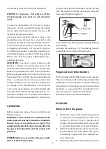
1.
Place the suction tube/suction hose in a
flushing bucket filled with clean flushing fluid:
either mineral spirits (for oil-based materials),
lacquer thinner (for lacquers), water (for
water-based materials), or soapy water (for
converting from oil-based to water-based
materials).
2.
Separate the drain tube from the suction tube
(if they are clipped together) and place it in an
empty waste bucket.
3.
Open the priming valve.
4.
Ensure that the unit is turned off and the
pressure control knob is at the minimum
(anticlockwise ) setting. Plug the unit in.
5.
Turn the unit on.
6.
Turn the pressure control knob clockwise to
increase the pressure just enough to let the
pump run.
7.
Allow the pump to run and watch the fluid
discharging from the drain tube. Allow the
fluid to discharge until completely clean
flushing fluid is coming out. The hose and gun
also need to be flushed when changing colors
or when switching between different types of
materials/paints:
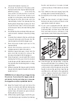
8.
With the tip and tip guard removed from the
gun, point the gun into the waste bucket and
hold the trigger open.
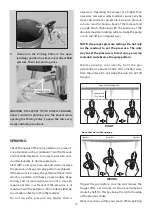
WARNING: Risk of static sparking, fire
or explosion Hold the metal part of the
gun firmly to the side of a metal pail. All
solvent pails must be conductive metal
material and properly grounded. Do not
place on a non conductive insulating
surface unless a ground wire is added to a
true earth such as a metal water pipe.
9.
Close the priming valve.
10.
Allow the pump to run and watch the fluid
discharging from the gun. Allow the fluid to
discharge until completely clean flushing fluid
is coming out.
WARNING: Do not release the gun trigger
during this process. If you release the
trigger, pressure will build in the line and
when you re-squeeze the trigger there will
be a splashback hazard.
11.
Then turn the unit off and turn the pressure
control knob anticlockwise back to the
minimum setting. Then unplug the unit.
The pump is now clean and ready to be
primed with material.
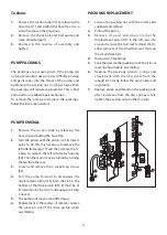
PRIMING
This is a high pressure pump and all air and
unwanted fluids must be bled out of the pump and
lines before spraying can begin.
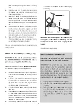
Ensure that the tip and tip guard are removed from
the gun and the trigger is locked.
To prime
1.
Place the suction tube in the material bucket.
2.
Place the drain tube in a waste bucket and
open the priming valve.
3.
Ensure that the pressure control knob is in the
minimum position and the unit is switched off.
Plug the unit in and turn it on.
4.
Slowly turn the pressure control knob
clockwise to increase the pressure just enough
to let the pump run.
5.
Allow the pump to run and watch the fluid
discharging from the drain tube. Allow the
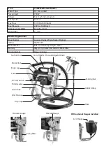
Summary of Contents for 700W Mechanical
Page 1: ...Original Instructions ...
Page 24: ......


