

16
HOURLY MAINTENANCE
We recommend after every hour of spraying, stop,
follow the Pressure Relief Procedure and perform
the following:
•
Add about 2 drops of throat Seal Oil to
lubricate the packings.
•
Clean the pump filter.
(if so equipped)
•
Clean the gun filter.
•
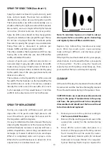
Clean the tip.
•
Clean the inlet strainer. As needed.
CAUTION: Never lay the pump on its back.
Material could flow backward and damage the
electronics or motor.
DAILY MAINTENANCE
1. Keep the displacement pump packing
nut
lubricated with throat seal oil at all times.
Add about five drops of oil to the top of the
pump at the beginning of each day. Then two
drops for every hour of spraying. The throat
seal oil helps protect the piston, rod and
packings.
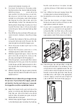
2. Inspect the packing nut daily.
If either of the
following conditions exists the packing nut
should be tightened:
a.
Seepage of material past the packing
is found.
b.
While the system is pressurized
during the intervals when the motor
is not running, the piston doesn't
hold its position. Rather, it tends to
slip upward.
To tighten the packing nut: Reach the tommy bar
through the opening and tighten the packing nut.
CAUTION: The packing nut should be
tightened just enough to stop leakage only, but
not any tighter. Overtightening will damage the
packings and reduce packing life.
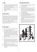
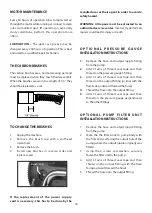
3. Clean the intake check ball and seat.
housing. Place the filter in the spray gun and
reassemble the unit by tightening the nut with
the wrench.
19.
Clean the exterior of the sprayer with a rag
soaked in the appropriate solvent.
20.
If flushing was with water, flush again with
mineral spirits to prevent corrosion inside the
pump.
CAUTION: Never leave water in the pump for any
length of time. Water will corrode the pump.
LONG TERM STORAGE
For long- term storage, fill the pump with a storage
solution made of a 50/50 mix of motor oil and
mineral spirits.
To fill the pump:
1.
Place the both the suction tube and drain tube
in a small quantity of storage solution.
2.
With the priming valve in the open position,
turn the machine on and turn the pressure
control knob just enough for the pump to run.
3.
Watch the drain tube and as soon as the storage
solution appears in the tube, shut the machine
off and close the priming valve. This will trap
the storage solution inside the pump to protect
it.
MAINTENANCE
Every 50 hours of operation blow compressed air
through the motor while running at no load to clean
out accumulated dust. (If operating in especially
dusty conditions, perform this operation more often.)
Summary of Contents for 700W Mechanical
Page 1: ...Original Instructions ...
Page 24: ......


