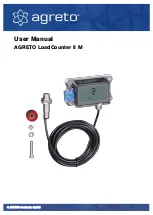
AGRETO LoadCounter II M
© AGRETO electronics GmbH
page:11
7
Assembly
Only start with the assembly once you have clarified whether a change in the
configuration is necessary for your application. Please read the chapter
"Configuration" before.
7.1
Positioning the sensor and the magnet
The mounting location of the sensor and the magnet must be chosen in such a
way that the magnet generates pulses in the sensor during the application
process of a load or transport process. The magnet must move past the front
end of the sensor at a distance of 5 to 8 mm.
Example scraper floor shaft on a manure spreader:
The magnet is attached to one of the scraper floor shafts. If there is no suitable
option here, the magnet can also be attached to the side of a chain wheel or a
flange. The sensor is attached to a frame part.
Example PTO shaft on a manure spreader:
The magnet is mounted on the trailer's PTO shaft stub, the flat bar for the
sensor on a frame part. For this type of mounting, the optionally available
magnetic ring can be used instead of the magnet.
Example dumper:
The magnet and the sensor are mounted at one point so that contact is made
at least once during lifting and once during lowering.
Example sliding wall on a push-off trailer:
The magnet and the sensor are mounted at one point in such a way that
contact is made at least once during pushing off of the load. A second contact
is made when the sliding wall is returned.

