5
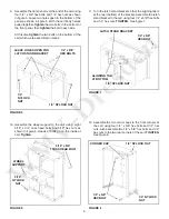
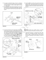
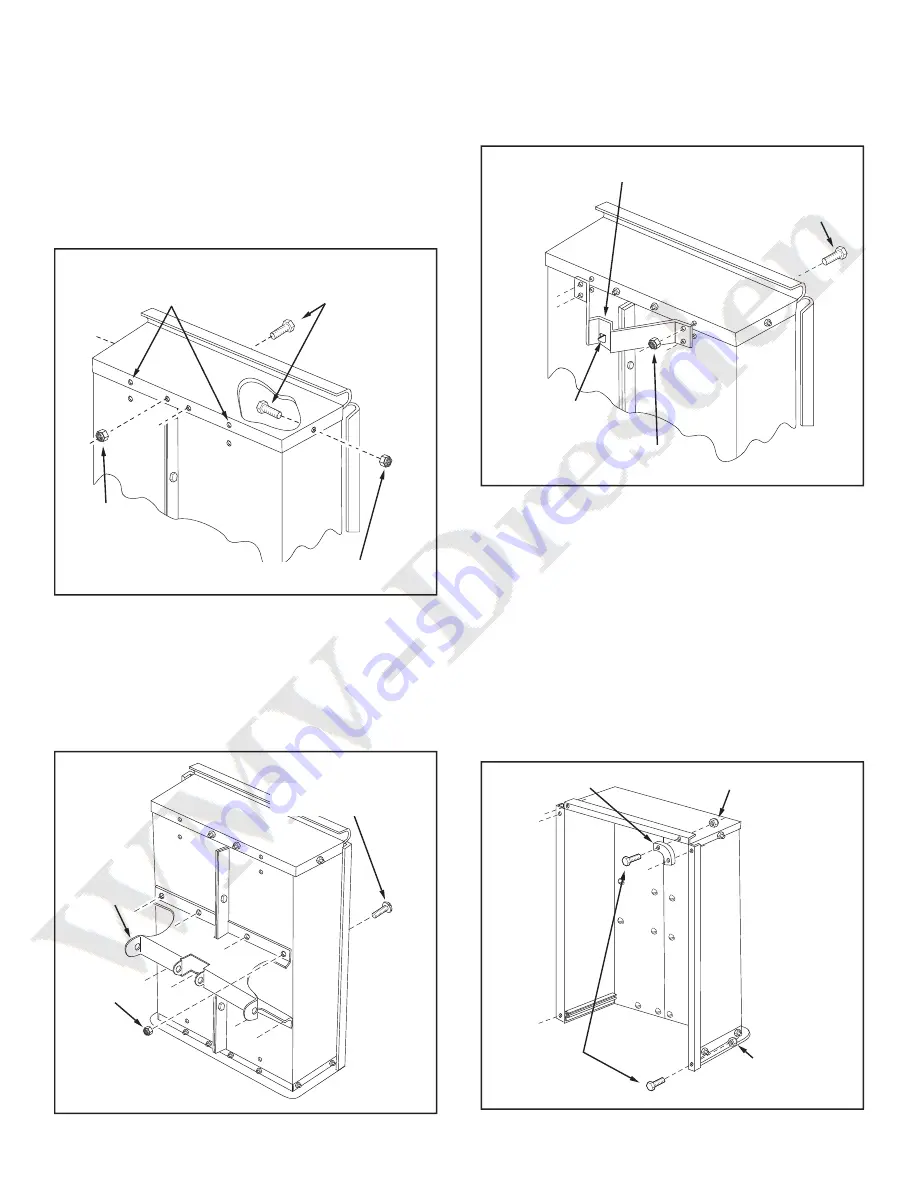
FIGURE 6
FIGURE 7
FIGURE 5
9. Assemble the front panel over the end of the cart using
four 1/4" x 5/8" hex bolts and 1/4" hex nuts as shown
in fi gure 5. Leave two holes open in the bottom of the
panel as shown in fi gure 5. With the cart body halves
pulled together,
tighten
the two bolts in the bottom of
the front panel, then
tighten
the bolt in each side.
At this time
tighten
the two bolts on the bottom of the
cart which were assembled in step 4.
FIGURE 8
10. Assemble the wheel support to the cart using eight
5/16" x 3/4" truss head bolts and 5/16" hex nuts as
shown in fi gure 6. Heads of bolts go on the inside of
cart.
Tighten.
12. Assemble the two corner caps to the front corners of
the cart using four 1/4" x 5/8" hex bolts and 1/4" hex
nuts. Also assemble two 1/4" x 5/8" hex bolts and 1/4"
hex nuts to the two rear corners of the cart.
TIGHTEN.
See fi gure 8.
11. Turn the latch stand bracket so that the aligning tab is
at the rear (bottom) of the bracket. Assemble the latch
stand bracket to the cart using four 1/4" x 5/8" hex bolts
and 1/4" hex nuts.
TIGHTEN.
See fi gure 7.
1/4" x 5/8"
HEX BOLTS
1/4"
NYLOCK
NUT
1/4" NYLOCK NUT
LEAVE HOLES OPEN FOR
LATCH STAND BRACKET
1/4" x 5/8"
HEX BOLT
LATCH STAND BRACKET
1/4" NYLOCK NUT
ALIGNING TAB
AT BOTTOM
CORNER CAP
1/4" x 5/8"
HEX BOLT
1/4" NYLOCK NUT
1/4" NYLOCK
NUT
5/16"
NYLOCK
NUT
WHEEL
SUPPORT
5/16" x 3/4"
TRUSS HEAD BOLT
Summary of Contents for 45-01003
Page 10: ...10 NOTES...


