background image

9

MAINTENANCE

CLEANING

• 

Clean engine as instructed in the engine manual.

• 

Clean wheels, finish, etc. Of all foreign matter.

• 

Keep finished surfaces and wheels free of all 
gasoline, oil, etc.

• 

Protect painted surfaces with automotive type wax.

We do not recommend using a garden hose to clean 
your unit unless the muffler, air filter and carburetor are 
covered to keep water out. Water in engine can result in 
shortened engine life.

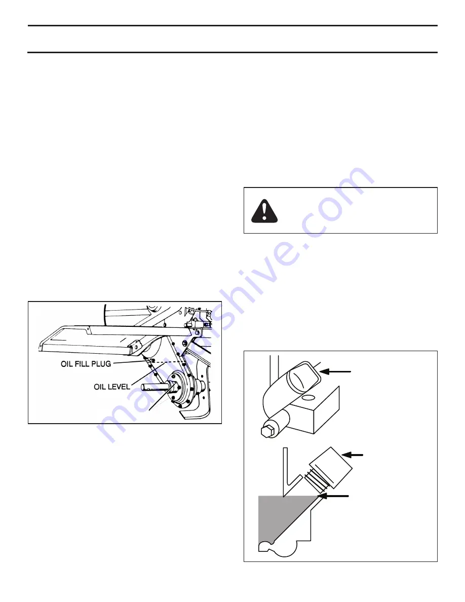
FiGURE 10

FiGURE 11

GREASE FITTING

WARNING: 


Always stop engine and 

disconnect spark plug wire before cleaning, 
lubricating or before performing any repairs 
or maintenance.

ENGINE MAINTENANCE

• 

Check 

oil level

 before each use and every 8 hours.

• 

Maintain engine oil as instructed in figure 11 below. 

• 

Service 

air cleaner

 every 25 hours under normal 

conditions. Clean every few hours under extremely 
dusty conditions. Poor engine performance and 
flooding usually indicates that the air cleaner should 
be serviced. To service the air cleaner, refer to the 
separate engine manual.

• 

Spark plug

 replacement is recommended every 100 

hours or yearly. Check the engine manual for correct 
plug type and gap specifications.

OIL

FULL OIL LEVEL

REMOVE OIL CAP

REPLACE CAP
AFTER FILLED

MUFFLER

Do not operate tiller without muffler. Do not tamper with 
exhaust system. Damaged mufflers or spark arresters 
could create a fire hazard. Inspect periodically and 
replace if necessary. If your engine is equipped with a 
spark arrester screen assembly, remove every 50 hours 
for cleaning and inspection. Replace if damaged.

TRANSMISSION LUBRICATION

Check the transmission oil level after first 5 hours of 
operation. Remove oil fill plug (figure 10). Oil level must 
be even with the plug hole (with tiller level). If necessary, 
add oil. Use SAE 30 non-detergent motor oil. Replace oil 
fill plug.

Check the transmission oil level after each 10 hours of 
operation.

NOTE:

 It is not necessary to change the oil in this tiller 

transmission. If for any reason it must be changed, oil 
capacity is 22 oz.

BEARING LUBRICATION

Grease the tine shaft bearings every 8-10 hours. Use a 
grease gun to apply about 10 pumps of General Purpose 
grease in the grease fittings. Wipe off excess grease that is 
forced out of the bearings. For dry and dusty environments, 
perform this lubricating procedure more often.

Summary of Contents for 45-03085

Page 1: ...tment Repair Parts FORM NO 40907 rev 9 13 12 CAUTION Read Rules for Safe Operation and Instructions Carefully Printed in U S A the fastest way to purchase parts www speedepart com IMPORTANT The engine is shipped without oil Oil must be added before starting the engine See Engine Maintenance on page 9 of this manual for instructions ...

Page 2: ... engineered and manufactured to give you the best possible dependability and performance Please read and retain this manual The instructions will enable you to assemble and maintain your tiller properly Always observe the SAFETY RULES MODEL NUMBER 45 03085 45 03086 SERIAL NUMBER _____________________________ DATE OF PURCHASE __________________________ THE MODEL AND SERIAL NUMBER WILL BE FOUND ON T...

Page 3: ...rtant Warnings Cautions and Notes are a means of attracting attention to important or critical information in this manual look for this symbol to point out important safety precautions it means attention become alert your safety is involved Never place hands or feet under or into rotating parts or concealed areas Keep hands and feet clearly away from tine elements belts pulleys etc while engine is...

Page 4: ...oved from the axle during unpacking See figure 2 3 8 NYLOCK NUT TO INSTALL THE TILLER TINE ASSEMBLIES Attach the floating hitch to the tractor s draw bar Refer to OPERATING INSTRUCTIONS on page 6 Remove the preassembled 3 8 x 2 hex bolt and 3 8 nylock nut from the L H Tine Assembly Slide the tine assembly onto the Transmission Axle on the left side of the tiller and secure with the hex bolt and ny...

Page 5: ...HITCH telescoping hitch limits shock loads to tractor RECOIL START HANDLE used to start the engine THROTTLE CONTROL controls engine speed FUEL SHUT OFF shuts of fuel to engine CHOKE CONTROL used when starting a cold engine DEPTH STAKE controls tilling cultivating depth know your tiller Compare the illustration below with your tiller to familiarize yourself with the location of various controls and...

Page 6: ...itch of tiller with a Hitch Pin and Hair Cotter Pin Fasten Hitch Bracket Extension to Tractor Drawbar with a 1 2 13 x 1 1 4 Hex Bolt and 1 2 Nylock Nut HAIR COTTER PIN 1 2 NYLOCK NUT HEX BOLT 1 2 13 X 1 1 4 HITCH PIN FLOATING HITCH HITCH BRACKET EXTENSION TRACTOR DRAWBAR BREAKING IN YOUR TILLER Break in your belts pulleys and the control before you actually begin tilling Start engine with tiller a...

Page 7: ...ine of tilling but may vary depending upon soil conditions In virgin soil the tiller should be started in the shallowest depth position and lowered one position at a time after each pass in each position If the soil is extremely hard and dry it may be desirable to cross till an area at shallow depth first then till in the direction of planting rows on the second pass at the final depth Where possi...

Page 8: ... tines and belts for wear A new spark plug and clean air filter assure proper air fuel mixture and help your engine run better and last longer Before each use Check engine oil level Check tine operation Check for loose fasteners lubrication Keep unit well lubricated See LUBRICATION CHART LUBRICATION CHART Figure 9 Change oil every 25 hours when operating the engine under heavy load or in high temp...

Page 9: ...ry 100 hours or yearly Check the engine manual for correct plug type and gap specifications OIL FULL OIL LEVEL REMOVE OIL CAP REPLACE CAP AFTER FILLED Muffler Do not operate tiller without muffler Do not tamper with exhaust system Damaged mufflers or spark arresters could create a fire hazard Inspect periodically and replace if necessary If your engine is equipped with a spark arrester screen asse...

Page 10: ...2 and 13 IMPORTANT Do not move or remove the belt guide If the position of the belt guide is accidentally altered return it to the correct setting 6 1 2 above the tine shield support plate Remove the screw from the top of the belt guard Remove the hex nut from the rear of the guard Remove the belt guard to allow access to drive belt Disengage tine clutch lever and remove belt Reverse above procedu...

Page 11: ...RVICE STORAGE section of the Engine Manual TILLER Clean entire tiller See CLEANING in the MAINTENANCE section of the manual Inspect and replace belts if necessary See belt replacement instructions in the Service and Adjustments section of this manual Lubricate as instructed in the MAINTENANCE section of this manual Be sure that all nuts bolts and screws are securely fastened Inspect moving parts f...

Page 12: ...ngine overloaded Set depth stake and wheels for shallower tilling Partially plugged air cleaner Remove and clean or replace Dirty air screen Clean air screen Spark plug dirty improper gap or wrong type Replace spark plug and adjust gap Oil in gasoline Drain and refill tank and carburetor Clogged fuel tank Remove and clean Poor compression Major engine overhaul ENGINE OVERHEATS Low oil level or dir...

Page 13: ... Oil Plug 9 HA20138 3 Bearing Cap 10 HA20137 4 Roller Bearing 11 47598 19 Washer Faced Lock Nut 1 4 20 12 66269 1 Tine Shaft and Sprocket Assembly 13 42088 1 Roller Chain Short ref part no qty description 14 66270 1 Idler Shaft Assembly 15 66271 1 Input Shaft Assembly 16 HA20145 1 Seal 17 42087 1 Roller Chain Long 18 66720 1 Drive Housing RH includes items 9 10 19 HA20134 1 Belt Guard and Idler Br...

Page 14: ... 23 82 87 88 83 89 39 46 79 59 59 23 30 14 75 B B C C 66 28 38 A A 85 86 41 67 45 KE EP AW AY FR OM RO TA TIN G TIN ES RO TA TIN G TIN ES WI LL CA US E INJ UR Y D A N G E R 3 6 KE EP AW AY FR OM RO TA TIN G TIN ES RO TA TIN G TIN ES WI LL CA US E INJ UR Y D A N G E R 3 6 DA NG ER TO AVO ID SER IOU S INJ URY DO NOT OPE RAT E WIT HOU T BEL T GUA RD AND ALL OTH ER SHI ELD S IN PLA NCE AND IN GO OD CO...

Page 15: ... 16 18 x 3 4 41 26559 1 Hitch Bracket Extension 42 714 0117 1 Pin Hair Cotter 5 32 43 26366 1 Fender Plate 44 43910 2 10 Washer 45 43351 1 Bolt Hex 1 2 13 x 1 1 4 ref part no qty description 46 40711 1 Nylock Nut 8 32 47 47600 1 Bolt Hex 5 16 24 x 1 48 HA5236 1 Pin Hitch 49 43062 1 Bolt 3 8 16 x 1 1 2 Hex Head 50 HA20918 2 Wheel 51 R74780828 1 Bolt 1 2 13 x 1 3 4 Hex Head 52 HA20670 1 Pivot Axle A...

Page 16: ...REPAIR PARTS Agri Fab Inc 809 South Hamilton Sullivan IL 61951 217 728 8388 www agri fab com 2001 Agri Fab Inc the fastest way to purchase parts www speedepart com ...

Reviews: