background image

9

USING THE SPRAYER

1.  Determine  the  application  rate  (gallons  per  1,000 

sq.  feet  or  gallons  per  acre)  based  on  the  chemical 
manufacturers recommendations. Use this rate to help 
select  the  pressure  setting  and  tractor  speed  in  the 
following instructions.

2.  Determine the approximate square footage of the area to 

be sprayed and estimate the number of gallons required. 
Do not fi ll tank with more solution than needed.

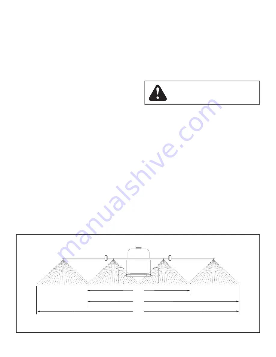
3.  Decide how wide a swath you wish to spray with each 

pass. Use just the two inside nozzles, or the two inside 
nozzles plus one outside nozzle, or use all four nozzles. 
The number of square feet covered with each pass will 
vary  depending  on  the  number  of  nozzles  used,  but 
the amount of solution applied per square foot will not 
vary as long as the same system pressure and speed 
of travel are used. Refer to fi gure 18.

FIGURE 18

WIDTH OF SPRAY PATTERN USING 2, 3 OR 4 NOZZLES

CAUTION:  Wear  eye  protection,  gloves 
and protective clothing when handling and 
working with lawn chemicals.

80"

160"

120"

OPERATION

BEFORE STARTING
It is important 
to test the boom and spray gun with plain 
water fi rst to check the sprayer for leaks and to set the spray 
pattern and nozzle pressure. If a leak should occur, thread 
tape may be used to better seal the fi tting.

PUMP PRESSURE SWITCH
The pump is equipped with a pressure switch. The pressure 
switch senses outlet pressure of the pump and will turn off 
the electrical power to the pump at a predetermined high 
pressure point (45 PSI). If the fl ow demand is very low,  the 
pump may reach this high pressure point and the switch will 
cause "cycling" (the pump cycles on and off rapidly). This is 
not a problem unless the pump continuously cycles within 
one second intervals for long periods of time.

ADJUSTING OPERATING PRESSURE
The sprayer is equipped with a "Y" fi tting containing two 
valves. The  bypass  valve  controls  the  fl ow  to  the  return 
(bypass) hose. The amount of fl ow through the return hose 
determines the operating pressure of the boom or the spray 
gun. Adjust the bypass valve while either the boom or the 
spray gun is in use to obtain the desired pressure, indicated 
by the pressure gauge. The tip chart on page 11 shows how 
different pressure settings affect boom application rates.

ON-OFF ADJUSTMENT OF BOOM NOZZLES
The boom valve on the "Y" fi tting controls the fl ow to all 
the boom nozzles. It should be either completely open or 
completely  closed. The  two  valves  located  on  the  boom 
will  turn  the  fl ow  on  or  off  to  each  outside  nozzle.  Each 
valve should be set either completely open or completely 
closed.

ADJUSTING SPRAY GUN NOZZLE
Turn the nozzle on the spray gun to adjust the spray from a 
cone shaped fi ne mist to a straight stream. The spray gun 
operating pressure should be controlled using the bypass 
valve on the "Y" fi tting. Maximum spray gun pressure can 
be attained when the boom is shut off.

Summary of Contents for 45-0325

Page 1: ...uctions Carefully OWNERS MANUAL 45 GALLON ATV SPRAYER Model No 45 03252 PRINTED IN USA FORM NO 40216 2 06 the fastest way to purchase parts www speedepart com IMPORTANT The wheel bearings are not prelubricated The wheel hubs must be filled with grease after the wheels are assembled to the axle ...

Page 2: ...ayer may affect your vehicle s braking and stability Be aware of your vehicle s capabilities Refer to the safety rules in the vehicle owner s manual concerning safe operation on slopes Be aware of changing conditions on slopes STAY OFF OF STEEP SLOPES 10 Operate at reduced speed on rough terrain along ditches and on hillsides to prevent loss of control 11 Follow maintenance and lubrication instruc...

Page 3: ...asher 1 O 4 Flat Washer 1 O 4 Flat Washer 1 O 4 Flat Washer 1 P 12 Flat Washer 3 8 P 12 Flat Washer 3 8 P 12 Flat Washer 3 8 P 12 Flat Washer 3 8 Q 2 Lock Washer 3 16 Q 2 Lock Washer 3 16 Q 2 Lock Washer 3 16 Q 2 Lock Washer 3 16 R 6 Lock Washer 3 8 R 6 Lock Washer 3 8 R 6 Lock Washer 3 8 R 6 Lock Washer 3 8 S 2 Cotter Pin 1 8 x 1 1 2 S 2 Cotter Pin 1 8 x 1 1 2 S 2 Cotter Pin 1 8 x 1 1 2 S 2 Cotte...

Page 4: ...en yet FIGURE 2 TOOLS REQUIRED FOR ASSEMBLY 2 7 16 Wrenches 2 1 2 Wrenches 2 9 16 Wrenches 1 Adjustable Wrench 1 Screwdriver 1 Pliers 1 Grease Gun 1 Remove all items from the carton and lay them out as shown on pages 2 and 3 2 Assemble the frame strap and the front frame angle to the bottom of the two side angles as shown in figure 1 Use eight 5 16 x 3 4 hex bolts and 5 16 nylock nuts Do not tighte...

Page 5: ... the nut securely enough to prevent leaking being careful not to damage the plastic parts Place the O ring inside the nylon cap and screw the cap onto the end of the drain body FIGURE 4 WHEEL 1 8 x 1 1 2 COTTER PIN SPACER 1 FLAT WASHER HITCH PIN 3 8 x 1 HEX BOLT 1 8 HAIRPIN COTTER HITCH BRACKET 3 8 NYLOCK NUT DRAIN BODY HOSE GASKET NYLON WASHER NYLON NUT O RING NYLON CAP 5 Assemble the axle throug...

Page 6: ... 15 Align the holes in the boom transport bracket with the holes in the ends of the boom mount assemblies as shown in figure 9 Fasten them together using two 5 16 x 1 hex bolts and 5 16 nylock nuts Tighten the bolts assembled in this step and in step 14 NOTE If the holes in the boom mount assemblies won t line up temporarily loosen the bolts which fasten the boom mount brackets to the frame 16 Asse...

Page 7: ...the strainer screen and then assemble the spray nozzle and the nozzle nut keeping the nozzle opening facing down while tightening See figure 12 23 Attach the hose assembly tee fittings to the boom using the same procedure as was used for the elbows See figure 12 RH SIDE VIEWED FROM REAR RH SIDE VIEWED FROM REAR FIGURE 11 FIGURE 13 VIEWED FROM FRONT FIGURE 14 NOTE To help prevent leaking use thread ta...

Page 8: ...e battery Connect the redwireonthefusedwireharnesstothepositiveposton the battery or the HOT connection on a vehicle switch or the ammeter The brown wire may be grounded or connected to the negative battery post See figures 16 and 17 IMPORTANT Keep wiring away from hot engine parts rotating parts and pinch points IMPORTANT Connect sprayer to 12 volt batteries only RETURN BYPASS HOSE 20 40 60 80 100...

Page 9: ...pressure switch senses outlet pressure of the pump and will turn off the electrical power to the pump at a predetermined high pressure point 45 PSI If the flow demand is very low the pump may reach this high pressure point and the switch will cause cycling the pump cycles on and off rapidly This is not a problem unless the pump continuously cycles within one second intervals for long periods of tim...

Page 10: ...ater and R V antifreeze through the entire plumbing Proper care and maintenance will prolong the life of the sprayer 4 Setthedesiredboompressure sprayingwithplainwater whilemakingpressureadjustments Forbestresultsstay in the 20 to 30 PSI range At 10 PSI the spray pattern begins to break up and at 40 PSI some drift develops Refer to the tip chart on page 11 5 Determinetheappropriatespeedatwhichtotr...

Page 11: ... 38 0 7 1 135 3 85 1 92 1 29 0 97 0 77 0 51 0 38 0 7 1 135 3 85 1 92 1 29 0 97 0 77 0 51 0 38 0 7 1 135 3 85 1 92 1 29 0 97 0 77 0 51 0 38 0 7 1 135 3 85 1 92 1 29 0 97 0 77 0 51 0 38 0 7 1 135 3 85 1 92 1 29 0 97 0 77 0 51 0 38 0 7 1 135 3 85 1 92 1 29 0 97 0 77 0 51 0 38 0 7 1 135 3 85 1 92 1 29 0 97 0 77 0 51 0 38 3 80 160 20 35 1 21 0 60 0 40 0 30 0 24 0 16 0 12 3 80 160 20 35 1 21 0 60 0 40 0...

Page 12: ...3 24 25 26 26 27 28 29 30 30 31 23 23 31 32 33 33 33 33 34 35 36 37 38 39 40 41 42 43 45 47 48 49 49 50 51 59 59 60 61 61 61 62 63 64 64 65 65 65 65 66 66 69 70 70 71 75 76 75 73 77 74 72 74 74 79 81 82 83 84 84 85 88 87 86 57 56 55 54 53 52 52 81 31 B B 80 80 80 80 25 C C 11 60 60 73 73 73 60 60 9 7 10 73 73 67 78 8 46 58 44 89 90 ...

Page 13: ...lt Hex 3 8 16 x 3 4 Lg 72 43003 6 Lock washer 3 8 73 HA21362 13 Nut Hex 3 8 16 Nylock 74 43070 12 Washer Flat 3 8 Std Wrt 75 43015 4 Nut Hex 3 8 16 Thread 76 49428 2 Bolt Hex 3 8 16 x 4 1 4 Lg 77 46959 2 Spring 78 43343 1 Pin Hair Cotter 1 8 4 79 43055 2 Pin Hair Cotter 3 32 3 80 726 0178 8 Tie Nylon 81 45072 3 Gasket 3 4 Garden Hose 82 45017 1 Hose Y with Valves 3 4 83 45071 1 Gauge 2 Pressure 84...

Page 14: ...14 NOTES ...

Page 15: ...NOTES ...

Page 16: ...16 REPAIR PARTS Agri Fab Inc 303 West Raymond Sullivan IL 61951 217 728 8388 www agri fab com the fastest way to purchase parts www speedepart com 2004 Agri Fab Inc ...

Reviews: