background image

9

STEP 19 - ATTACH HOPPER BAG

• 

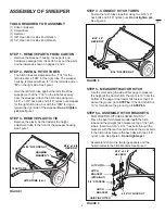
To attach the hopper bag to the sweeper, slide the 
ends of the bag arm tubes into the ends of the hitch 
tubes and secure with two 1/4" x 1-3/4" clevis pins 
and small hairpin cotters. See figure 21.

STEP 18 - ATTACH ROPE

• 

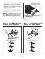
Secure the rope to the center of the upper rear 
hopper tube as shown in figure 20.

FIGURE 21

FIGURE 20

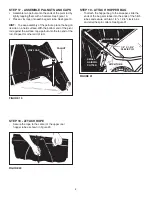
FIGURE 19

STEP 17 - ASSEMBLE PALNUTS AND CAPS

•  Assemble two palnuts onto the ends of the pivot rod by 

lightly tapping them with a hammer. See figure 19.

•  Place a vinyl cap onto each bag arm tube. See figure 19.

HINT:

  To ease assembly of the palnuts, place the bag on 

its side on a hard surface. With the bottom end of the pivot 
rod against the surface, tap a palnut onto the top end of the 
rod.  Repeat for other end of rod.

PALNUT

VINYL CAP

1/4" X 1-3/4" 
CLEVIS PIN 

SMALL 
HAIRPIN 
COTTER 

HITCH TUBE 

HITCH TUBE 

BAG ARM TUBE 

Summary of Contents for 45-03523

Page 1: ...S A FORM NO 41957 01 31 11 42 PROFESSIONAL LAWNSWEEPER CAUTION Read Rules for Safe Operation and Instructions Carefully the fastest way to purchase parts www speedepart com Model No 45 03523 OWNERS MANUAL Call 1 800 448 9282 for missing parts or assembly help ...

Page 2: ...and inspect vehicle and sweeper for damage after striking an object Repair any damage before continuing operation 9 Keep sweeper away from fire Excessive heat can damage the brushes and hopper bag and could cause the bag and its contents to burn 10 Before storing the sweeper always empty the hopper bag to avoid spontaneous combustion 11 Follow maintenance and lubrication instructions as outlined i...

Page 3: ...Screw 10 32 x 5 8 G 47810 13 Nylock Nut 5 16 H 47171 6 Nylock Nut 10 32 I 44917 2 Palnut J 23625 3 Small Spacer K 23368 2 Large Spacer L 48366 2 Clevis Pin 3 8 x 1 2 REF PART NO QTY DESCRIPTION M 48365 2 Clevis Pin 1 4 x 1 1 8 N 46867 2 Clevis Pin 1 4 x 1 3 4 O 142 1 Cotter Pin 1 8 x 3 4 P 43070 1 Washer 3 8 Q 43055 6 Hair Cotter Pin Small R 43343 1 Hair Cotter Pin Large S 43943 1 Grip T 44481 2 V...

Page 4: ...ts and 5 16 nylock nuts Repeat for the right hitch tube but with the 76R facing in toward the right side of the sweeper Do not tighten yet See figure 1 STEP 3 REMOVE PLASTIC TIE Remove the plastic tie that fastens the height adjustment tube to the front of the sweeper housing See figure 1 STEP 5 MEASURE TRACTOR HITCH Use the mark along the side of this page to measure the height of the tractor hit...

Page 5: ... See figure 4 STEP 7 TIGHTEN BOLTS Tighten the four bolts in figure 1 that fasten the hitch tubes to the sweeper housing Next tighten the two bolts in figure 2 that fasten the ends of the hitch tubes together Finally tighten the two bolts in figure 3 or 4 that fasten the hitch brackets to the hitch tubes STEP 8 ATTACH HEIGHT ADJUSTMENT PLATE Attach the height adjustment plate to the sweeper housin...

Page 6: ...ough the stitched flaps of the hopper bag starting at the center cut out in the top of the bag See figures 8 9 and 10 Repeat for the right hand upper hopper tube FIGURE 8 Slide the two upper hopper tubes together and line up the center holes as shown in figure 9 FIGURE 9 Right Left BAG FLAP UPPER HOPPER TUBE LEFT HAND SHOWN END HERE CENTER CUT OUT START HERE UPPER HOPPER TUBES PLASTIC PLUG Fasten ...

Page 7: ...hold tubes in place a short time and does not need to be replaced LOWER HOPPER TUBE HOPPER BAG BOTTOM UPPER HOPPER TUBE 3 8 x 1 2 CLEVIS PIN SMALL HAIR COTTER PIN STEP 13 ATTACH BAG BOTTOM Assemble the bag retainer and the bag frame strap to the front edge of the bag bottom Place the bag retainer on top and the bag frame strap underneath the bag bottom Fasten together using six 10 x 5 8 screws and...

Page 8: ...m using the snaps See figure 15 FIGURE 15 FIGURE 16 SNAP FLAP SUPPORT RODS STEP 16 ASSEMBLE HOPPER ROD AND BAG ARM TUBES If the hole in the side of the upper hopper tubes is covered over by the bag locate the hole by touch It is approximately midway along the side of the bag Pierce holes through the stitched bag flaps where the holes in both hopper tubes are located See figure 17 UPPER HOPPER TUBE...

Page 9: ...FIGURE 21 FIGURE 20 FIGURE 19 STEP 17 ASSEMBLE PALNUTS AND CAPS Assemble two palnuts onto the ends of the pivot rod by lightly tapping them with a hammer See figure 19 Place a vinyl cap onto each bag arm tube See figure 19 HINT To ease assembly of the palnuts place the bag on its side on a hard surface With the bottom end of the pivot rod against the surface tap a palnut onto the top end of the ro...

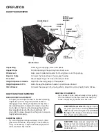
Page 10: ...ANT To obtain the best performance from your sweeper arrange the spacers so that the sweeper bag is approximately level with the ground and approximately 5 to 7 off the ground as shown in figure 22 GROUP B For vehicles with hitches having 10 to 13 ground clearance GROUP A For vehicles with hitches having 8 to 10 ground clearance APPROXIMATELY LEVEL 5 TO 7 FROM SURFACE BRUSH HEIGHT ADJUSTED APPROXI...

Page 11: ...handle in position when locked Hitch Bracket Connects the sweeper to the towing vehicle Adjusts for various height tractor hitches BRUSH HEIGHT ADJUSTMENT To adjust your sweeper brushes to the best operating height lift up on the height adjustment handle to disengage it from the height adjustment strap Move the handle forward or backward to raise or lower the brush Refer to the Know Your Sweeper f...

Page 12: ...ft bearing twice a year with a few drops of light weight oil See figure 23 HEIGHT ADJUSTMENT SLOT HEX BOLT OIL BEARINGS HERE FLAT WASHER FIGURE 23 Clean the sweeper and hopper bag thoroughly to help prevent rust and mildew To collapse the hopper bag for storage remove the two hopper support rods from the rear of the hopper Store in a dry area CAUTION Before storing the sweeper always empty the hop...

Page 13: ...d mixing of parts The R H and L H ratchet gears are not interchangeable Make notes on the position of washers and snap rings during disassembly 1 Remove only one wheel from the sweeper 2 Remove the retaining rings and washers which hold the ratchet gear onto the brush shaft 3 Remove the gear by sliding it off the brush shaft Look for the drive pin which may fall out of the brush shaft when the rat...

Page 14: ...37 55 6 C D 43 47 65 57 61 69 68 22 2 10 9 8 20 20 20 31 19 58 20 1 19 7 3 17 18 25 26 26 28 29 32 34 37 55 27 22 11 12 13 C 15 36 14 35 16 24 71 40 72 41 42 39 68 5 44 68 54 46 62 53 4 71 53 38 62 45 73 72 70 A A 59 20 66 50 64 67 49 51 63 56 30 52 60 48 E D E B B 23 21 ...

Page 15: ...0 2 Spacer Small 33 48652 1 Gear Pinion R H not shown 34 48651 1 Gear Pinion L H 35 43866 4 Bolt Hex 1 4 20 x 5 8 36 43177 4 Lock Washer 1 4 37 64559 2 Dust Cover Assembly REF PART NO QTY DESCRIPTION 38 46732 1 Lower Hopper Tube R H 39 46733 1 Lower Hopper Tube L H 40 46734 1 Upper Hopper Tube R H 41 46735 1 Upper Hopper Tube L H 42 46738 1 Hopper Bag 43 46739 1 Wind Screen 44 25430 1 Bag Frame St...

Page 16: ...the fastest way to purchase parts www speedepart com REPAIR PARTS Agri Fab Inc 809 South Hamilton Sullivan IL 61951 217 728 8388 www agri fab com 2005 Agri Fab Inc ...

Reviews: