background image

7

5

5

Z

Y

Q

Q

L

R

S

F

OFF

1 –

2 –

3 –

4 –

5 –

6 –

7 –

8 –

9 –

10 –

SETTING "5"

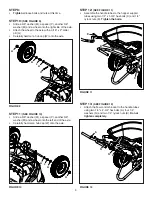
sTeP 14: 

(see FIGure 13)

• 

Insert the end of the flow control rod (5) with double 
bend through the hole in the drive link bracket (Z) and 
then twist the rod so that the end points down.

FIGure 13

sTeP 15: 

(see FIGure 14)

• 

Insert the other end of the flow control rod (5) 
through the hole in the control arm on the flow control 
assembly. Secure it with a 1/4" washer (N) and a 3/32" 
x 3/4" cotter pin (I).

FIGure 14

sTeP 16: 

(see FIGure 15)

• 

Assemble the adjustable stop (S) to the flow control 
bracket using the 1/4" x 3/4" carriage bolt (F), a nylon 
washer (L) and the wing nut (R).

• 

Install the handle grips (Q) onto the handles.

• 

Install the control grip (Y) onto the flow control arm.

FIGure 15

FIGure 16

sTeP 17: 

(see FIGure 16)

• 

Set the adjustable stop at "5" and move the control 
arm back against it.

• 

Slide the control bracket along the handle tube until 
the flow plate in the bottom of the hopper is open half 

way.

• 

Tighten the bolts and nuts attaching the control bracket 
to the handle tubes. 

• 

Make sure the flow plate will open and close 
completely. Readjust if necessary.

N

I

5

Summary of Contents for 45-04621

Page 1: ...s Carefully ATTENTION Lire et suivre attentivement les instructions et consignes de s curit de cette notice PRECAUCION Lea cuidadosamente los Procedimientos e Instrucciones para la Operaci n Segura de...

Page 2: ...perate the broadcast spreader without proper instructions 2 Do not permit children to operate the broadcast spreader 3 Wear eye and hand protection when handling and when applying lawn or garden chemi...

Page 3: ...er Pin 3 16 x 2 H 1 43093 Cotter Pin 1 8 x 1 1 2 I 1 44101 Cotter Pin 3 32 x 3 4 J 1 48934 Hairpin Agitator K 13 47189 Hex Nut 1 4 Nylock L 5 1543 69 Washer Nylon M 4 R19212016 Washer 5 8 N 9 43088 Wa...

Page 4: ...E FIGURE 2 Insert the bushing V into the cross brace 4 Attach the cross brace to the hopper support tubes using two 1 4 x 2 1 2 hex bolts B and 1 4 nylock nuts K Do not tighten completely STEP 3 SEE F...

Page 5: ...hex bolt E and a 1 4 nylock nut K Tighten and then loosen the nut just enough for the drive link bracket to pivot STEP 7 SEE FIGURE 7 Place the hopper onto the hopper support tubes inserting the verti...

Page 6: ...is time STEP 11 SEE FIGURE 10 Slide a 5 8 washer M a spacer P another 5 8 washer M and a wheel onto the left end of the axle Carefully hammer a hub cap W onto the axle STEP 12 SEE FIGURE 11 Assemble t...

Page 7: ...URE 14 STEP 16 SEE FIGURE 15 Assemble the adjustable stop S to the flow control bracket using the 1 4 x 3 4 carriage bolt F a nylon washer L and the wing nut R Install the handle grips Q onto the hand...

Page 8: ...flow plate 6 Always release the bail to close the flow plate before turning around or stopping the spreader 7 If fertilizer is accidentally deposited too heavily in a small area soak the area thorough...

Page 9: ...he gear box and the vertical spreader shaft 9 Re assemble the gearbox housings and secure them with the clips 10 Oil the idler wheel and the axle bushings at least once a year or more often as needed...

Page 10: ...uctions correctes 2 Ne laissez pas des enfants se servir de l pandeur centrifuge 3 Portez des lunettes protectrices et des gants quand vous manipulez et quand vous pandez des produits chimiques pour l...

Page 11: ...ie aux tubes support de tr mie l aide de quatre boulons hexagonaux de 1 4 po x 1 3 4 po C de rondelles de 1 4 po N de rondelles en nylon L et d crous autofrein s de 1 4 po K Serrez les quatre boulons...

Page 12: ...bit 6 Toujours rel cher la barre pour fermer la plaque de d bit avant tout virage ou arr t de l pandeur 7 En cas de d p t accidentel d une grande quantit d engrais sur une petite surface bien imbiber...

Page 13: ...ositions de la roue dent e d entra nement et du grand pignon par rapport au petit pignon d terminent le sens de rotation de l agitateur Veillez les remonter dans leurs positions d origine Se r f rer l...

Page 14: ...aplique productos qu micos para el c sped o jard n ESPA OL Preste atenci n a este s mbolo ya que indica precauciones de seguridad importantes Significa atenci n Est alerta Su seguridad est en juego Pr...

Page 15: ...e del esparcidor PASO 8 VEA LA FIGURA 8 Acople la tolva a los tubos de soporte de la tolva usando cuatro pernos hexagonales de 1 4 pulg x 1 3 4 pulg C arandelas de 1 4 pulg N arandelas de nylon L y tu...

Page 16: ...or est equipado con un deflector lateral b jelo para volear a un solo lado del esparcidor 10 En condiciones de bastante humedad puede requerirse el uso de una cubierta de vinilo para tolva a fin de qu...

Page 17: ...ceite encima de la caja de cambios y el eje vertical del esparcidor 9 Vuelva a ensamblar las carcasas de la caja de cambios y aseg relas con los sujetadores 10 Coloque aceite en los bujes de los neum...

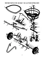
Page 18: ...22 53 36 54 39 42 44 55 2 52 5 14 15 16 17 18 35 41 32 14 10 18 9 9 15 12 4 3 43 28 29 29 30 34 31 33 43 45 40 45 46 14 15 16 17 15 12 10 26 11 27 27 11 26 14 6 6 7 7 8 19 20 21 13 23 24 25 22 27 27 2...

Page 19: ...1 27322 Bracket Flow Control 25 1 24856 Arm Flow Control 26 6 1543 69 Washer Nylon 3281 x 75 27 9 43088 Washer 1 4 Std 312 x 734 28 1 26711 Shaft Spreader REF QTY PART NO DESCRIPTION 29 2 47212 Housin...

Page 20: ...o the Universal Copyright Convention and the Berne convention No part of this document may be reproduced or transmitted in any form or by any means electronic or mechanical including photocopying or r...

Reviews: