background image

29

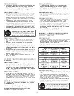
RAISING AND LOWERING
•  To raise, push down on the lift handle until the snow 

thrower locks in the raised transport position.

•  To lower, push down slightly on the lift handle and pull 

the trigger. With the trigger pulled, slowly lower the 
snow thrower until it reaches the ground.

CUSTOMER RESPONSIBILITIES

•  Read and follow the maintenance schedule and the maintenance procedures listed in this section. 

Service Dates

  Check for loose fasteners 


  Check scraper and shoes for wear   


X


Cleaning 

    X

  Lubrication Section 


  MAINTENANCE SCHEDULE
 

Fill in dates as you

  complete regular service.

Bef

ore each use

After each use

Ev

ery season

Bef

ore stor

age

LUBRICATION

  Oil all pivot points on the snow thrower.

•  Oil the pivot points of the two idler arms on the clutch/

idler assembly.

•  Apply penetrating oil to the control cables of the 

discharge chute.

•  Apply a good grade of spray lubricant to the trigger 

assembly and the chute tilt control assembly.

CAUTION

:   Do not operate the snow 

thrower without the rear weight attached 
to the tractor to provide extra traction and 
stability.

MAINTENANCE

CHECK SCRAPER AND SHOES FOR WEAR

(Refer to figures 59 and 60 on page 30)

•  The scraper plate and skid shoes on the bottom of the 

snow thrower are subject to wear. To prevent damage 
to the spiral auger housing, replace plate and shoes 
before wear is excessive.

REMOVING SNOW 
Snow removal conditions vary greatly from light fluffy 
snowfall to wet heavy snow. Operating instructions must 
be flexible to fit the conditions encountered. The operator 
must adapt the lawn tractor and snow thrower to depth of 
snow, wind direction, temperature and surface conditions.
•  Before beginning operation, thoroughly inspect the 

area of operation and remove all door mats, sleds, 
boards, wires and other foreign objects.

•  The spiral auger speed is directly related to engine 

speed. For maximum snow removal and discharge, 
maintain high engine r.p.m. (full throttle). It is advisable 
to operate the lawn tractor at a slow ground speed 
(1st gear) for safe and efficient snow removal.

•  In deep, drifted or banked snow it will be necessary to 

use full throttle and a slow ground speed (1st gear). 
Drive forward into the snow, depress the tractor's 
clutch-brake pedal and allow the spiral auger to clear 
the snow. Repeat this method until a path is cleared. 
On the second pass, overlap the first enough to allow 
the snow thrower to handle the snow without repeated 
stopping and starting of forward motion.

•  In extremely deep snow, raise the snow thrower from 

the ground to remove the top layer and drive forward 
only until the tractors front tires reach the uncleared 
bottom layer of snow. Depress the tractor's clutch-
brake pedal and allow the spiral auger to clear the 
snow. Reverse the tractor and lower the snow thrower 
to the ground. Drive the tractor forward until the snow 
again becomes too deep. Repeating this process into 
and out of drifts will eventually clear even the deepest 
of snow piles.

•  If the snow thrower becomes clogged with snow or 

jammed with a foreign object, disengage the snow 
thrower immediately and shut off the tractor engine. 
Unclog the snow thrower before resuming operation.

OPERATING TIPS

•  Discharge snow down wind whenever possible.
•  To help prevent snow from sticking to the snow thrower, 

allow the snow thrower to reach outdoor temperature 
before using it. A light coat of wax may also be applied 
to the inside surface of the snow thrower housing and 
discharge chute.

•  Use tire chains to improve traction.
•  Use rear wheel weights to improve traction.
•  Before the first snowfall, remove all stones, sticks and 

other objects which could become hidden by the snow. 
Permanent obstacles should be marked for visibility.

•  Overlap  each  pass  slightly  to  assure  complete  snow 

removal.

DANGER

:   Shut off engine and 

disengage snow thrower before 
unclogging discharge chute. Unclog using 
a wooden stick, not your hands.

Summary of Contents for LST42C-669

Page 1: ...miento Piezas SOPLADOR DE NIEVE DE 42 106 cm OWNERS MANUAL MANUEL DU PROPRI TAIRE SOUFFLEUSE NEIGE 42 PO 106 cm AVERTISSEMENT Lire et suivre attentivement les instructions et consignes de s curit S cu...

Page 2: ...2 ENGLISH 8 ESPA OL 32 FRAN AIS 44 DEUTSCH 56 ITALIANO 68...

Page 3: ...ge Bolt 5 16 x 3 4 L 4 Shoulder Bolt M 2 Shoulder Bolt REF QTY DESCRIPTION N 2 Shear Bolt spare parts O 7 Lock Washer 3 8 P 7 Washer 1 4 Q 6 Washer 5 16 R 8 Washer 1 2 S 1 Washer 3 8 Thin T 3 Washer 3...

Page 4: ...rquilla de 3 32 GG 2 Pasador de traba HH 1 Tapa pl stica II 2 Tirante de Nylon JJ 2 Cadena tensora KK 2 Reflector de cola LL 1 Espaciador peque o MM 1 Espaciador grande NN 1 Polea R F QT DESCRIPTION A...

Page 5: ...5 16 x 1 3 4 I 2 Chiavarda a testa rotonda da 5 16 x 1 1 4 J 4 Chiavarda a testa rotonda da 5 16 x 1 RIF QT DESCRIZIONE K 2 Chiavarda a testa rotonda da 5 16 x 3 4 L 4 Vite con gambo parzialmente file...

Page 6: ...dle and Cable 10 Cable Bracket 11 L H Hanger Bracket Outside Mounting 12 R H Hanger Bracket Outside Mounting 13 Clutch Idler Assembly 14 V Belt Drive Short 46989 15 V Belt Drive Long 48138 16 V Belt A...

Page 7: ...Kabel CONTENUTO DEI CARTONI 1 Bracci di sospensione 2 2 Piastra laterale sinistra 3 Piastra laterale destra 4 Staffa antirotazione 5 Asta di inserimento Non usato in alcuni modelli 6 Fissatore della...

Page 8: ...equipment is to be used and remove all door mats sleds boards wires and other foreign objects Use extreme caution when op erating on or crossing gravel surfaces Never direct discharge at bystanders o...

Page 9: ...nd check for the cause Vibration is generally a warning of trouble Stop the engine whenever you leave the operating position before unclogging the snow thrower or making any adjustments or inspections...

Page 10: ...l instructions Mark all loose parts and save for reassembly Remove the tractor hood Refer to your tractor owner s manual for removal instructions CAUTION Beforestartingtoassemblethe snow thrower remov...

Page 11: ...the bolt that goes through the plate INSTALL HANGER BRACKETS AND SHOULDER BOLTS TO OUTSIDE OF FRAME STEP 5 SEE FIGURE 5 Remove the bolt if present in the hole directly behind the brake rod on the lef...

Page 12: ...actor Using the wrong length belt may cause premature bearing or belt failure STEP 10 SEE FIGURE 10 Two different length drive belts are included with your snow thrower Tractors with manual attachment...

Page 13: ...wo shoulder bolts M assembled to the outside of the tractor frame Lift the front of the assembly and attach it to the R H and L H hanger brackets using two pivot lock pins GG and 1 8 hairpin cotters E...

Page 14: ...ly Attach a 3 32 hairpin cotter FF to the chain placing it in the fifth link from the spring CHAIN L H SIDE 3 32 HAIR COTTER PIN FF 5TH LINK LEFT SIDE 3 8 HEX LOCK NUT Z SPRING RIGHT SIDE ATTACH SPRIN...

Page 15: ...s the 3 32 hairpin cotter in the chain will allow Secure the chain in this position by inserting a 1 8 hairpin cotter EE through the chain IMPORTANT Do Not assemble the drive belt around the outside o...

Page 16: ...lt J without a nut The bracket fastened to inside of frame must remain in place FRONT SUSPENSION BRACKET REPLACE BOLT IF PRESENT REMOVE BOLTS IF PRESENT FIGURE 20 RIGHT SIDE VIEW INSTRUCTIONS FORTRACT...

Page 17: ...g a 3 8 x 1 carriage bolt G and a 3 8 flanged nut X Bolt head goes on inside of tractor frame Repeat for the R H side STEP 28 SEE FIGURE 28 Assemble a shoulder bolt L and 3 8 flanged nut X to the R H...

Page 18: ...RM SUSPENSION ARM TRUNNION CC REMOVE EXTENSION BOLT AND NUT IF PRESENT STEP 30 SEE FIGURE 30 Attach the two suspension arms to the inside of the clutch idler assembly using two 5 16 x 3 4 hex bolts C...

Page 19: ...OLT 3 8 THIN WASHER S NEW ENGINE PULLEY KEEPER WITH ORIGINAL BOLT NUT AND WASHER STEP 34 SEE FIGURE 34 Assemble the short V belt onto the engine pulley and then onto the large pulley on top of the clu...

Page 20: ...RE 35 Attach the two suspension arms to the rear of the clutch idler assembly using two 5 16 x 3 4 hex bolts C 5 16 washer Q and 5 16 nylock nuts Y for each arm Place the arms on the outside of the fr...

Page 21: ...nut that secure the keeper Attach the new pulley keeper supplied with the snow thrower reusing the original bolt washer and nut NOTE Some tractors may already be equipped with a pulley keeper that is...

Page 22: ...below to select the correct drive belt for your type tractor The part number is printed on the outside of the belt Set aside the belt that is not for your tractor to avoid accidentally using it 55 BE...

Page 23: ...s Hook the assembly s notched arms onto the two shoulder bolts you assembled to the inside of the tractor frame Lift the front of the assembly and attach it to the R H and L H hanger brackets using tw...

Page 24: ...the lift release cable tilt the snow thrower forward onto the spiral auger FIGURE 47 RIGHT SIDE VIEW 5 16 NYLOCK NUT Y 5 16 x 1 3 4 HEX BOLT B ASSEMBLY OF THE SNOW THROWER STEP 50 SEE FIGURE 49 Tilt t...

Page 25: ...he plastic chute keepers Place the plastic cap HH onto the short end of the anti rotation bracket Position the crank rod spiral see figure 51 so that it does not rub against the bottoms of the notches...

Page 26: ...lation of the attachment pin until you have assembled the belt as instructed in steps 56 and 57 ATTACHING SNOW THROWER TO TRACTOR BEFORE INSTALLING THE AUGER BELT STEP 56 SEE FIGURE 55 The auger belt...

Page 27: ...HAIRPIN COTTER EE LEFT SIDE OF TRACTOR FLAT PULLEY CLUTCH IDLER ASSEMBLY REAR REFLECTORS KK ATTACH REFLECTORS TO REAR FENDER STEP 59 SEE FIGURE 58 If your tractor is not equipped with rear reflectors...

Page 28: ...eared Refer to the Service and Adjustments section Make sure the tractor engine has the correct oil for winter operation SAE 5W 30 Refer to tractor owner s manual HOW TO START YOUR SNOW THROWER The tr...

Page 29: ...For maximum snow removal and discharge maintain high engine r p m full throttle It is advisable to operate the lawn tractor at a slow ground speed 1st gear for safe and efficient snow removal In deep...

Page 30: ...to keep the housing and the scraper plate level See figure 59 LIFT RELEASE CABLE ADJUSTMENT If the lift rod does not lock the snow thrower securely in the transport position loosen the upper hex nut o...

Page 31: ...gure 54 on page 26 Lock the snow thrower s lift handle in the down position to decrease belt tension Release the spring tension from the auger belt idler arm on the bottom of the clutch idler assembly...

Page 32: ...to sobre superficies con grava Nunca utilice el soplador de nieve cerca de recintos acristalados autom viles pozos con ventana huecos grandes en el terreno o similares sin haber ajustado adecuadamente...

Page 33: ...gla general la vibraci n es un indicador de que existe alg n problema IMPORTANTE Es necesario contar con pesas en las ruedas traseras y cadenas para ruedas para brindar tracci n adicional y estabilida...

Page 34: ...al derecha con el ngulo hacia afuera a los tres orificios que se encuentran en la parte delantera del bastidor del tractor utilizando tres pernos de cabeza de hongo de 3 8 x 1 G tres arandelas de 1 2...

Page 35: ...los sujetadores de la polea del motor o fuera del perno del sujetador que se encuentra cerca de la gran polea Contin e con el paso 48 en la p gina 38 ESTA SECCI N ES S LO PARA TRACTORES CON EMBRAGUE...

Page 36: ...na arandela de 3 8 T al exterior de la placa lateral de cada lado asegur ndolas con una tuerca con brida de 3 8 X INSTALACI N DE LOS SOPORTES DE SUSPENSI N Para poder trabajar mejor haga descender los...

Page 37: ...embrague polea libre utilizando dos pernos de cabeza de hongo de 5 16 x 3 4 K y tuercas nylock de 5 16 Y Utilice los dos orificios delanteros del soporte del cable si su tractor tiene una cortadora de...

Page 38: ...o de la cadena tensora del lateral izquierdo hacia afuera tanto como permita el pasador de horquilla de 3 32 FF Asegure la cadena en esta posici n insertando un pasador de horquilla de 1 8 EE por el o...

Page 39: ...a correa de la barrena viene premontada sobre las poleas del alojamiento del soplador de nieve Aseg rese de que la correa pase sobre la parte superior de la polea de la barrena y que luego recorra un...

Page 40: ...manuales o el dispositivo del embrague en los embragues el ctricos Consulte el manual del usuario del tractor PRECAUCI N Nunca dirija la descarga hacia personas que lo est n observando o ventanas No p...

Page 41: ...a con la velocidad del motor Para obtener una m xima remoci n y descarga de la nieve mantenga elevadas las rpm del motor acelerador abierto por completo Se recomienda hacer funcionar el tractor para c...

Page 42: ...de manera segura en la posici n de transporte afloje unas vueltas la tuerca de cabeza hexagonal superior que se encuentra en el soporte de elevaci n y ajuste la tuerca de cabeza hexagonal inferior Co...

Page 43: ...azo de la polea libre de la correa de la barrena que se encuentra en la base del conjunto de embrague polea libre Retire la correa de transmisi n de la barrena del conjunto de embrague polea libre Ver...

Page 44: ...paillassons luges planches c bles et autres objets trangers Faire preuve d extr me pr caution en travaillant sur des surfaces en gravier ou en les traversant Ne jamais orienter le conduit d jection v...

Page 45: ...cause du probl me Les vibrations sont g n ralement un avertissement IMPORTANT Desmassesd quilibrageetdescha nesantid rapantes doivent tre pos es aux roues arri re pour que le tracteuraitunetractionetu...

Page 46: ...ns de carrosserie de 3 8 x 1 po G trois rondelles de 1 2 po R voir la remarque et trois crous embase de 3 8 po X Pour le trou arri re utiliser un boulon de carrosserie de 5 16 x 1 po J une rondelle de...

Page 47: ...d crous m caniques de s curit de 5 16 po Y pour chaque bras Placer les bras l ext rieur du ch ssis avec les crans vers l arri re TAPE 15 VOIR LA FIGURE 15 Retourner l ensemble embrayage et galet tende...

Page 48: ...de de deux boulons de carrosserie de 3 8 x 1 po G et des crous embase de 3 8 po X Les t tes des boulons vont l int rieur du ch ssis R p ter pour le c t droit Sur les tracteurs sans support de repose p...

Page 49: ...ser la courroie de m canisme d entra nement entre le boulon hexagonal et le galet tendeur plat avec le c t plat de la courroie contre la poulie Resserrer le boulon hexagonal Entourer la courroie autou...

Page 50: ...l attache en nylon qui relie la courroie de m canisme d entra nement de la tari re au carter d jection en laissant la courroie autour des poulies Retirer l attache en nylon qui relie la bielle d incl...

Page 51: ...en V de la courroie doit tre en phase avec les rainures des poulies en V INSTALLER L AXE D ATTELAGE TAPE 58 VOIR LA FIGURE 54 Soulever l avant de la souffleuse afin d aligner les trous des plaques de...

Page 52: ...r la bielle d inclinaison des goulottes dans le sens contraire des aiguilles d une montre pour faire tourner la goulotte vers la droite Pour contr ler la distance laquelle la neige est projet e la sec...

Page 53: ...r le tracteur et abaisser la souffleuse au sol Faire avancer le tracteur jusqu ce que la neige devienne nouveau trop profonde En r p tant ce processus d aller et venue m me les amas de neige les plus...

Page 54: ...VATION Si la barre d l vation ne bloque pas en toute s curit la souffleuse en position de transport faire plusieurs tours pour desserre l crou hexagonal sup rieur sur le support du bras d l vation et...

Page 55: ...rt de tension du bras de renvoi de la courroie de la tari re au bas de l ensemble embrayage et galet tendeur Enlever la courroie du m canisme d entra nement de la tari re de l ensemble embrayage et ga...

Page 56: ...eren und alle Fu matten Schlitten Bretter Dr hte und sonstigen Fremdobjekte sind zu entfernen Beim Betrieb auf bzw beim berqueren von Kiesoberfl chen ist u erste Vorsicht walten zu lassen Der Auswurf...

Page 57: ...er Ursache daf r zu suchen Im Allgemeinen ist Vibration ein Warnzeichen f r Probleme WICHTIG Beim Einsatz dieser Schneefr se sind Radgewichte an den hinteren R dern sowie Schneeketten zu verwenden um...

Page 58: ...3 Schritt gefordert wird SEITENPLATTEN INSTALLIEREN 3 SCHRITT SIEHE ABBILDUNG 3 Die rechte Seitenplatte Biegung nach au en zeigend mit Hilfe der drei 3 8 x 1 Schlossschrauben G drei 1 2 Unterlegscheib...

Page 59: ...RITT SIEHE ABBILDUNG 13 Den Keilriemen zuerst auf der Motorrolle anbringen und dann auf der gro en Rolle oben auf der Baugruppe Kupplung Umlenkrolle Der Riemen muss innerhalb der Keilriemenhalter und...

Page 60: ...enden Alle Schrauben anziehen und f r die linke Seite wiederholen HINWEIS Falls sich die Schraube frei beweglich in das vordere Loch einf hren l sst ist eine 3 8 Flanschmutter X auf der Schraube anzub...

Page 61: ...u enseite des Keilriemenhalters oder des Haltebolzens f hren Mit dem 48 Schritt auf Seite 62 fortfahren KABELBEDIENTE MANUELLE ZUSATZGER TEKUPPLUNG 35 SCHRITT SIEHE ABBILDUNG 35 Die zwei Aufh ngungsar...

Page 62: ...anheben und sie unter Verwendung von zwei Schwenksteckbolzen GG und 1 8 Haarnadelsplinten EE an der rechten und linken Aufh ngerhalterung anbringen 47 SCHRITT SIEHE ABBILDUNG 46 Den Keilriemen zuerst...

Page 63: ...tiftes warten bis Sie den Keilriemen wie in den Schritten 56 und 57 beschrieben angebracht haben VOR INSTALLATION DES SCHNECKENKEILRIEMENS 56 SCHRITT SIEHE ABBILDUNG 55 Der Schneckenkeilriemen wird au...

Page 64: ...ngshebel des Traktors bei manuellen Kupplungen bzw den Kupplungsschalter f r elektrische Kupplungen entkuppeln Siehe Bedienungsanleitung Ihres Traktors ACHTUNG Niemals den Auswurf auf Umstehende und F...

Page 65: ...tigen und der Spiralschnecke erlauben den Schnee zu r umen Dieses Verfahren solange wiederholen bis ein Pfad frei ger umt ist Beim zweiten Durchgang empfiehlt es sich diesen hinreichend mit dem erste...

Page 66: ...g 59 JUSTAGE DES HEBERFREIGABEKABELS Falls die Heberstange die Schneefr se nicht sicher in der Transportstellung arretiert die obere Sechskantmutter auf der Heberhalterung um einige Umdrehungen l sen...

Page 67: ...ung 54 auf Seite 26 Den Hebergriff der Schneefr se in der unteren Stellung verriegeln um die Spannung des Riemens zu senken Die Federspannung vom Schneckenriemenspannrollenarm an der Unterseite der Ba...

Page 68: ...vi ed altri corpi estranei Esercitare estrema cautela durante l uso dello spartineve su superfici inghiaiate o il loro attraversamento Non orientare mai il getto di neve in direzione degli astanti n p...

Page 69: ...i sono sintomi di problemi IMPORTANTE I pesi delle ruote posteriori e le catene per pneumatici sonoarticolinecessariperassicuraremiglioretrazione e stabilit al trattore quando si usa questo spartineve...

Page 70: ...lla fase 3 INSTALLAZIONE DELLE PIASTRE LATERALI FASE 3 VEDERE LA FIGURA 3 Serrare la piastra del lato destro la piegatura rivolta all esterno ai tre fori frontali nel telaio del trattore usando tre ch...

Page 71: ...DERE LA FIGURA 14 Attaccare i due bracci di sospensione alla parte posteriore del gruppo innesto pulegge folli usando due bulloni esagonali C da 5 16 x 3 4 e due bulloni nylock Y da 5 16 per ogni brac...

Page 72: ...onda G da 3 8 x 1 e i dadi a colletto X da 3 8 Le teste dei bulloni vanno sul lato interno del telaio del trattore Ripetere l operazione per il lato destro Sui trattori senza staffe poggiapiedi Trovar...

Page 73: ...a cinghia motrice da 55 140 cm con stampato il no 46989 della cinghia NON USARE l altra cinghia Allentare leggermente il bullone esagonale vicino alla puleggia folle piatta Installare la cinghia in ba...

Page 74: ...sollevamento con un dado esagonale al di sopra ed un dado esagonale ed una rondella elastica al di sotto della fessura Serrare i dadi regolandoli in modo da eliminare allentamenti nel cavo Fare riferi...

Page 75: ...dell innesto e delle pulegge folli Ruotare il braccio della puleggia folle verso il lato sinistro Porre la cinghia della coclea intorno alla puleggia posteriore e tra le due pulegge sul braccio delle...

Page 76: ...l funzionamento nel periodo invernale SAE 5W 30 Fare riferimento al manuale del proprietario del trattore COME AVVIARE LO SPARTINEVE A TURBINA Il trattore deve rimanere fermo con il motore funzionante...

Page 77: ...ndizioni di sicurezza In presenza di profondi banchi o ammassi di neve sar necessario usare il massimo regime ad una velocit a terra lenta 1ma marcia Guidare in avanti nella neve sollevare il pedale f...

Page 78: ...AMENTO Se l asta di sollevamento non blocca sicuramente lo spartineve a turbina in posizione di trasporto allentare il dado esagonale superiore sulla staffa di sollevamento di alcuni giri e serrare il...

Page 79: ...are la tensione della cinghia dal braccio delle pulegge folli della cinghia della coclea sul fondo del gruppo innesto pulegge folli Rimuovere la cinghia motrice della coclea dal gruppo innesto pulegge...

Page 80: ...80 PARTS REPAIR PARTS FOR MODEL LST42C 669 42 SNOW THROWER...

Page 81: ...ring Split 3 4 35 24279 2 Skid Shoe 36 48015 4 Washer Nylon 37 784 5618 2 Housing Bearing 38 24393 1 Bracket Chute Crank REF PART QTY DESCRIPTION NO NO 39 24281 1 Bracket Idler 40 49933 2 Shoulder Bol...

Page 82: ...82 REPAIR PARTS FOR MODEL LST42C 669 42 SNOW THROWER 67 36 60 57 61 65 58 62 11 65 58 58 62 63 32 33...

Page 83: ...ate Side L H 34 49916 1 Tube Lift Handle 35 49912 1 Trigger and Lift Cable Assembly REF PART QTY DESCRIPTION NO NO 36 43070 2 Washer 3 8 37 710 1233 1 Screw Oval 10 24 x 1 38 46446 1 Grip Handle 39 47...

Page 84: ...2 Washer 25 43063 3 Hex Bolt 5 16 18 x 1 26 46989 1 Belt V Type Drive 55 48138 1 Belt V Type Drive 56 27 47846 1 Belt V Type Auger 28 47044 1 Pulley V Type 4 29 47025 1 Hex Bolt 5 16 18 x 3 1 2 30 434...

Page 85: ...manual CAUTION DO NOT OPERATE YOUR TRACTOR AND SNOW THROWER ON A SLOPE IN EXCESS OF 10 DEGREES BE SURE OF YOUR TRACTOR S TOWING AND BRAKING CAPABILITIES BEFORE OPERATING ON A SLOPE AVOID ANY SUDDEN TU...

Page 86: ...AS DE 10 VERIFIQUE LA CAPACIDAD DE SU TRACTOR PARA REMOLCAR Y FRENAR ADECUADAMENTE AN TES DE OPERAR EN UNA PENDIENTE EVITE GIROS O MANIOBRAS BRUSCAS CUANDO OPERA EN UNA PENDIENTE UN POSTE DE CORRIENTE...

Page 87: ...pour r f rence future Utilisez ce guide afin de d terminer si une pente est s curitaire pour l utilisation de votre tracteur et de la charrette Voir galement les instructions incluses dans votre manu...

Page 88: ...LS IHREN TRAKTOR UND DIE SCHNEEFR SE AN EINEM GEF LLE VON MEHR ALS 10 GRAD BETREIBEN VERGEWISSERN SIE SICH VOR DEM BETRIEB AN EINEM GEF LLE DER ZUG UND BREMSF HIGKEITEN IHRES TRAKTORS AN EINEM GEF LLE...

Page 89: ...colo CAUTION DO NOT OPERATE YOUR TRACTOR AND SNOW THROWER ON A SLOPE IN EXCESS OF 10 DEGREES BE SURE OF YOUR TRACTOR S TOWING AND BRAKING CAPABILITIES BEFORE OPERATING ON A SLOPE AVOID ANY SUDDEN TURN...

Page 90: ...o the Universal Copyright Convention and the Berne convention No part of this document may be reproduced or transmitted in any form or by any means electronic or mechanical including photocopying or r...

Reviews: