Brush Cutter 4500 Hydro
21
3. Devices and Operating Elements
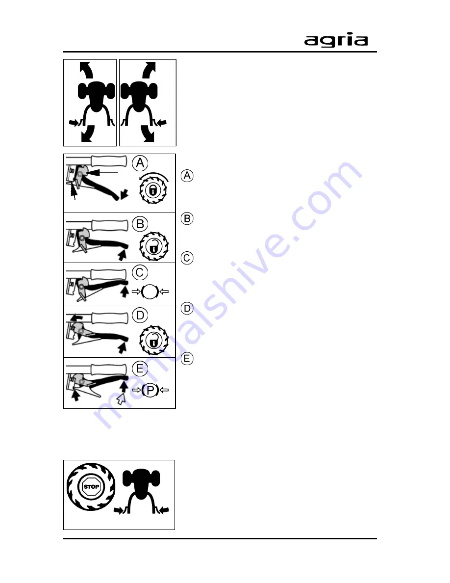
Steering Brake
By use of the steering brake levers (A/28 and A/29)
the drive to the inside-facing wheel is switched off
and then braked, the outside-facing wheel main-
tains its speed.
Steering lever settings
Wheel drive on
- Steering lever pushed down
- both locking levers (Y, Z) opened
Wheel drive off
- Steering lever in the central position
- both locking levers (Y, Z) opened
Steering brake on
- wheel drive switched off
- Steering lever pushed up to the stop
- both locking levers (Y, Z) opened
Coasting Operation
- wheel drive switched off
- both steering levers in the central position
- locking lever (Y) set to locked position
Park brake
- wheel drive switched off
- both steering levers pushed up to the stop
- locking lever (Z) set to locked position
Quick stop
l
By moving both steering levers (A/28+ A/29) to
the central position the operating drive is switched
off
l
By moving both steering levers to the stop the
driving wheels are braked (application recommen-
ded, for instance when engine is overloaded)
- the equipment drive (PTO shaft) remains unaffec-
ted.
A/x
A/x
Y
Z
A/28
A/29


