background image

4 Commissioning and Operation 

Meadow mower 

agria 5300


33 

Mowing 

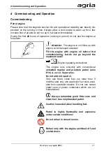
 Check the function of the safety circuit. See page 48. 

- Start the machine only when the safety circuit is working!

Remove the knife protection bar 

Lubricate the cutter bar 

Wear hearing protection and safety shoes 

Start  the  engine  as  described  at  "Starting  the 

engine". See page 31 

Switch on the wheel drive 

Switch on the mower drive 

Traction drive at forward movement - clutch lever 

(C/5)  released,  press  safety  lever  (C/4)  slowly 

down, and accelerate at the same time. 

Summary of Contents for 5300

Page 1: ...nal Operating In structions Meadow mower agria 5300 Petrol engine Honda 5300 535 Before commissioning please read the operating instructions and note the safety and warning information Operating Instructions No 998 478GB 02 20 ...

Page 2: ...ations and dimensions provided in these operating instructions are non binding No claims may be derived from them We reserve the right to make im provements without amending this manual Scope of delivery please check Meadow mower base unit Handlebar with grip screw 1 pair driving wheels Cutter bar Tool kit Original Operating Instructions Original engine operating instructions Machine identity card...

Page 3: ...rd reverse Fast Slow Closed locked Open unlocked Visual inspection Attachment point for re covery lashing towing Wear protective gloves Wear safety shoes Fan cooling Oil lubrication point Grease lubrication point Maintenance interval Before each start up After each cleaning in particularly with a high pressure cleaner Annually See separate engine op erating instructions agria Service contact your ...

Page 4: ...4 agria 5300 Designation of parts ...

Page 5: ... Cutter bar linkage 13 Lubricating nipple for cutter bar linkage 14 Gearbox oil filler plug check plug 15 Gearbox cover gearbox oil drain hole 16 Driving wheel 17 Catch spring for driving wheel Fig B 1 Air filter 2 Carburettor 3 Fuel tank cap 4 Fuel tank 5 Choke lever 6 Engine type no 7 Starter handle 8 Fan grille 9 Exhaust with contact guard 10 Sparking plug sparking plug connector 11 Oil dipstic...

Page 6: ...gine 18 Speed regulating lever 19 Safety circuit 19 Engine stop switch 20 Traction drive 20 Clutch 21 Wheel drive 21 Mower drive 22 Steering bar 22 Driving wheels 23 Cutterbar 25 Attachment points 26 4 Commissioning and Operation 27 Commissioning 27 Before starting the engine 29 Danger zone 30 Starting the petrol engine 31 Stopping the petrol engine 32 Mowing 33 Mowing on slopes 35 Safety instruct...

Page 7: ...Storage 53 6 Troubleshooting and Remedies 54 Petrol engine 54 Machine 56 7 Decommissioning Disposal 58 Inspection and Maintenance Overview 60 Electric diagram of petrol engine 62 Lubrication plan 63 Paints Wear parts 64 Declaration of Conformity 65 Designation of parts 66 ...

Page 8: ...lebar Unscrew and remove hexagon head screw 3 and hexagon nut 4 Swing up the steering bar 2 Insert the hexagon head screw 3 through the bores Install and tighten the hexagon nut 4 Pull the hand lever for wheel switching 6 to position 0 and let it engage The wheel drive is now switched off and the machine can be moved without motor drive Pull the machine rearwards out of the cardboard box Attach th...

Page 9: ...vance of the operating servicing and mainte nance conditions stipulated by the man ufacturer Unauthorized changes to the machine especially to the safety equipment may lead to increased levels of danger which would rule out any manufacturer liability for resulting damage When using the machine on public roads and when being transported the national road traffic regulations of the relevant country ...

Page 10: ... signs provide important information for safe operation please observe them for your own safety The engine must be switched off for transport on motor vehicles or trailers outside the working area Be careful with rotating tools keep a safe distance Be careful with coasting tools Before you start working on them wait until they have come to a complete stop There is a risk of crushing and shearing o...

Page 11: ... be cleaned with appropriate tools There may be tension in the drive train as a result of the blockage which is why you should resolve the blockage carefully In the event of any damage to the ma chine or the add on device shut down the engine immediately and have the damage repaired In the event of any malfunctions to the steering stop and park the machine immediately Have the fault resolved witho...

Page 12: ... of the impact when the vehicle hits an obstacle Maintenance and cleaning Only trained specialist personnel who can carry out professional maintenance and repair may carry out this work Do not carry out maintenance and clean ing with the engine running When working on the engine always remove the ignition key if present and also the spark plug connector in the case of petrol engines Protective dev...

Page 13: ... vomiting occur consult a doctor immediately In the event of con tact with the eyes rinse immediately with plenty of water Avoid inhaling vapours Read and observe enclosed instructions Before disposing of opened and seem ingly empty pressurized tins make sure they are completely empty Empty them in a well ventilated area safe from sparks and flames Dispose of tins as hazardous waste if necessary W...

Page 14: ...d observe the operat ing instructions and safety instructions Prior to starting cleaning maintenance or repair work switch off the engine and pull the sparking plug connector Keep a safe distance to the mower knives when the engine is running When working with the machine wear individual hearing pro tection Wear protective gloves Wear safety shoes ...

Page 15: ... BP Energear Hypo Driving speed Forward 3 0 km h Reverse 2 3 km h Mowing unit Central crank drive rock shaft speed 920 rpm stroke dyn approx 56 mm Steering bar Vibration damped height adjustable lateral adjustment without tools Weight Without cutter bar 70 0 kg With cutter bar 105 cm 84 0 kg With cutter bar 125 cm 89 5 kg Tyres 3 50 6 field tread Tyre pressure 0 8 bar Noise Sound pressure level at...

Page 16: ...2 Technical Data 16 Meadow mower agria 5300 Dimensions mm a 470 b 630 e 280 h 860 1080 l 1550 m 910 or 1050 corresponding to cutter bar ver sion s 375 s Twin tyres 762 A 525 A Twin tyres 857 ...

Page 17: ...em contactless fixed ignition point radio interference suppressed to VDE 0879 Valve play with cold engine intake 0 15 0 02 mm exhaust 0 20 0 02 mm Starting device Cable pull starter Fuel Commercially available car petrol Octane rating see engine operating instructions Fuel consumption 313 g kWh Capacity of the fuel tank 3 1 l Air filter Dry filter cartridge with foam prefilter Carburettor Throttle...

Page 18: ...e engine at a higher speed than necessary for the work in hand applies even after the running in period High speeds are detrimental to all engines and significantly reduce their service life This especially ap plies for no load operation Over revving the engine letting it roar can result in immediate damage Cooling The engine is cooled with an air blower Keep the fan grille at the cable pull start...

Page 19: ...fety lever C 4 This establishes a non positive connection between engine and gearbox The safety circuit must be operated in two steps 1 Pull the stop pawl upwards disengage 2 Press the safety lever down When the wheel drive or the mowing drive is switched on the wheels or mowing tools respectively start moving immediately when the safety lever is pressed down This must be borne in mind during oper...

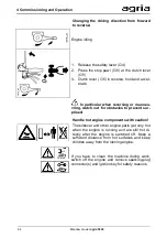
Page 20: ...e The meadow mower is equipped with a for ward reverse gearshift that is integrated in the clutch and is manually operated with the clutch lever C 5 Reversing 1 Release the safety lever C 4 2 Press the stop pawl C 6 at the manually operated clutch lever C 5 3 Pull the manually operated clutch lever fully up Traction drive in neutral Manually operated clutch lever C 5 pulled approx half Forward mov...

Page 21: ...off Wheel switching hand lever C 11 pulled up and stop pawl engaged With running engine use the following procedure to switch the wheel drive Press the stop pawl C 6 at the manually operated clutch lever C 5 Pull the manually operated clutch lever C 5 up to the centre position neutral and hold it there Disengage the stop pawl C 10 Move the wheel switching hand lever C 11 down Slowly release the ma...

Page 22: ...crew 2 from the square clamping piece 3 and pull it out of the articulated bar element Adjust the handlebar to the desired level and fit it into the matching hole in the articulated bar element Insert the hexagon head screw Screw it into the square clamping piece ensure that the nose of the clamping piece is locked in the oblong hole of the locating jaw of the articu lated bar element in the lower...

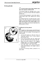
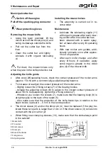
Page 23: ...wheel is en gaged in a toothing and is thus connected to the wheel shaft for driving Installing the driving wheels Install the driving wheels with field tread such that the tip of the tyre tread points in driving direction seen from above This provides full traction power Lift the catch spring 1 and put it down at assembly position Fig J front annular groove at the hub Fit the driving wheels onto ...

Page 24: ...ly Neutral Push both driving wheels outwards and let the catch springs engage in the outer ring grooves Fig L Drive with differential like effect Engage one driving wheel in the inner ring groove Fig K and the second driving wheel in the outer ring groove Fig L neutral Wrap protection Wrap protection tubes are fitted to the wheel shaft on both sides between the gearbox and the driving wheel Fig M ...

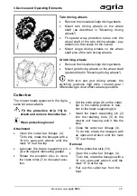
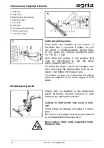
Page 25: ...ed in the Agria sales list are available Fit the protective strip 10 to attach and remove the cutter bar Wear protective gloves Attachment Open the cutter bar linkage 4 To do this rotate the hexagon with a 13 mm open end wrench until the mark A is at the top Lubricate the beam supporting pin 2 with organic lubricating grease Rotate the eccentric disc to move the crank roller 7 to its lowest posi t...

Page 26: ...r With cutter bar version S the existing skid must be repositioned so that the bulge points upwards see Fig O To adjust the height loosen the hexagon nuts O 1 and move the gliding soles O 2 as re quired Then tighten the hexagon nuts To achieve a clean cut ensure that the gliding soles are adjusted to the same height on both sides Straps must be fastened to the attachment points for towing recovery...

Page 27: ...l the engine with engine oil before first commissioning but do not go beyond the maximum level Engine operating instructions This engine runs smoothly with conventional unleaded regular and premium petrol also E10 as well as Super plus Do not add oil to petrol Only use fresh clean fuel no older than 3 months and only use approved fuel cans avail able from specialist dealers Do not use rusted metal...

Page 28: ...el Use a suitable filling device Do not fill the fuel tank until it overflows Leave approximately 5 mm space to allow the fuel to expand If you spilled fuel push the machine away from the spilled liquid before you start the engine Bowden cable for the safety function Check the Bowden cable of the safety function for damage Replace a defective Bowden cable immediately ...

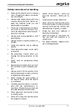
Page 29: ... machine into operation after all protective devices have been mount ed are functional and in protection position Prior to starting up the machine ensure that the protective covers are installed correctly The implements must be secured properly Handle hot engine components with caution The silencer and other engine parts get very hot when the engine is running and are still hot di rectly after the...

Page 30: ...the danger zone of the machine during startup and operation is not permit ted If the operator notices that people or animals are in the working area the machine must be switched off immediately and not restarted until this area is clear The user is responsible for third parties in the working area entire area to be worked on Hazard area meadow mower V S 2 m 1 m ...

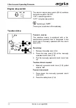
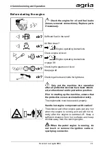
Page 31: ...t CHOKE when the engine is hot Engine at operating temperature Leave CHOKE in normal operating position Switch off the mower drive 3 Set engine stop switch B 14 to operating position ON 4 Set speed regulating lever C 9 to approxi mately 1 3 throttle 5 Start the engine from outside the hazard zone Hold the starter rope at the starter handle B 7 and pull it out vigorously and rapidly to start the en...

Page 32: ...rized use and rolling away Pull off the sparking plug connector Use wheel chocks First allow the engine to cool down be fore storing in closed rooms Do not put the choke in the choke posi tion to stop the engine danger of fire In a dangerous situation set the engine stop switch to OFF to switch off the engine If you want to shut down the machine for a longer time do not stop the engine at the engi...

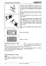
Page 33: ...rcuit is working Remove the knife protection bar Lubricate the cutter bar Wear hearing protection and safety shoes Start the engine as described at Starting the engine See page 31 Switch on the wheel drive Switch on the mower drive Traction drive at forward movement clutch lever C 5 released press safety lever C 4 slowly down and accelerate at the same time ...

Page 34: ...versing or manoeu vring watch out for obstacles to prevent sur prises Handle hot engine components with caution The silencer and other engine parts get very hot when the engine is running and are still hot di rectly after the engine is switched off Keep a sufficient distance from hot surfaces and keep children away from the running engine If you have to clean the machine during work switch off the...

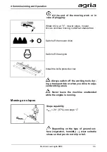
Page 35: ...e mower drive Switch off the engine Install the knife protection bar Always switch off the working tools dur ing a transport ride or when you drive to adja cent working areas Never leave the machine unattended while the engine is running Mowing on slopes Slope capability max 20 37 see page 17 Depending on the type of ground sur face vegetation humidity wear suitable shoes so that you do not slip o...

Page 36: ...ing ma chine The machine is too heavy You can not hold it If possible steer the machine across the slope Release the safety lever to activate the safety circuit Turn the machine only in uphill direc tion Mowing flat surfaces Mowing on slopes Parking the machine on a slope The machine rolls downhill when you set the wheel switching to O on a slope Always position the machine such that it is across ...

Page 37: ...ly careful when you turn the machine or pull it towards your self Always switch off the working tools during a transport or when you drive to adjacent working areas Never change the basic setting of the engine Never allow the engine to overspeed Carefully start the engine in accord ance with the manufacturer s in structions Ensure that your feet are at a safe distance from the tools Never approach...

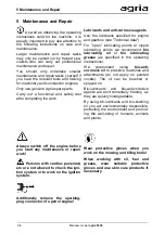
Page 38: ...le lubricating points we recommend bio lubricating oil or bio lubricating grease as specified in the operating instructions We recommend using bio anti corrosive oil to preserve machines and attachments do not apply on painted covers The oil can be brushed or sprayed on Bio lubricants and bio anti corrosive agents are environmentally friendly as they are quickly biodegradable By using bio lubrican...

Page 39: ...ration Only with the engine switched off and on level ground Clean the oil filler plug and its environment Unscrew the oil filler plug wipe the oil dip stick with a clean cloth and reinsert it do not screw it in Remove the oil dipstick and check the oil level If the oil level is below the lower min mark fill in engine oil see Technical data up to the rim of the oil filler neck max ...

Page 40: ...Ensure proper disposal of the used oil Check the sealing rings Replace if nec essary Tighten the oil drain plug Oil filing volume and quality see Technical da ta If possible use a funnel or a similar fixture to fill in the oil Fuel hoses Replace every 2 years Replace leaking plastic hoses immediately Air cooling system After long periods of operation the cooling sys tem can be obstructed with dust...

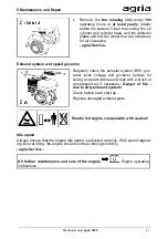
Page 41: ...check the exhaust system B 9 gov ernor lever linkage and governor springs for soiling and plant debris and clean with a brush or compressed air if necessary Danger of fire due to dirty exhaust system Check before each start up Replace damaged exhaust parts Handle hot engine components with caution Idle speed Always ensure that the engine idle speed is adjusted correctly With speed regulat ing leve...

Page 42: ...he gearbox oil Change the gearbox oil once a year and when it is still at operating temperature Clean oil filler plug A 14 and gearbox cover A 15 and their environment to prevent dirt from getting into the gearbox To drain the oil remove gearbox cover 3 or A 15 from the gearbox housing unscrew two hexagon socket screws Collect the used oil in a suitable container and dispose of it properly Check t...

Page 43: ...ve tyre pressure Install the wheels such that the tip of the tyre pattern points in driving direction seen from above This provides full traction power Only skilled specialists are allowed to repair and change tyres using suitable installation tools Continuously check the wheel shaft for grass wraps and remove them Remove the driving wheels if necessary Prior to mounting the driving wheels yearly ...

Page 44: ...Cleaning Immediatelyafter each mowing opera tion clean the cutter bar thoroughly with water To do this remove the mower knives so that above all the dirt accu mulated between the knife blades can thoroughly be removed Afterwards lubricate all sliding parts with organic lubricating oil or with organic lubricating grease Spray the cutter bar with organic anti corrosion oil when the machine is not in...

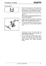
Page 45: ... mower knives with the support of the knife driver from the front onto the crank block Fold down the knife holder Press down the knife holders h in the di rection of the arrow f while you are tightening the clamping screws c very tightly 70 Nm with a long ring spanner Check whether the knife guide needs to be adjusted Adjust if nec essary Adjusting the knife guide To adjust knife projection d and ...

Page 46: ...some organic grease to the driver pins 4 of the mower knife Adjusting the knife guide After every 25 operating hours check the contact pressure of the rocker arms approx 150 N with a commercially available spring balance To increase or readjust the contact pressure of the rocker arms Slightly loosen the 2 fixing screws 7 of the bearing bodies Actuate the adjusting screws 8 to adjust to the correct...

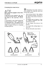
Page 47: ...junction with a cup shaped grind ing pen with a diameter of 25 mm and a length of approx 35 mm or a special sharpening device Sharpening the mower knives is very important for achieving clean and trouble free mowing Only the face side of the grinding pin is used for grinding moving from the back of the knife to the tips of the knives The blades must not heat up They are useless annealed and soft w...

Page 48: ...hen you release the safety lever C 4 and the clutch lever C 5 The clutch must engage when you actuate the safety lever C 4 up to the stop at the handle The clutch must not slip If neces sary check the Bowden cable and adjust it at the Bowden cable adjusting screw Release the locknut Adjust the adjusting screw as required Tighten the locknut to the hand lever bear ing agria Service Clutch lever for...

Page 49: ...unning in period after initial startup and after the clutch V belt has been replaced X 3 5 mm Bowden cable in hand lever bearing inserted in down position Adjustment Remove shaped spring 2 and remove the cable pull end 3 with the adjusting pin 4 from the retainer in the hand lever Screw the adjusting pin in out until there is a distance X or idling at position 0 Reinsert the cable pull end with th...

Page 50: ...lever C 4 such that the distance between the outer diameter of V belt pulley I and the outer diame ter of rubber roller II is 5 mm Actuate the safety lever for forward move ment With the safety lever pressed down adjust tension roller III in the direction of the arrow until the V belt is tensioned Fit the belt guide D 7 see fig D Install the belt guard D 8 This requires the clutch lever to be set ...

Page 51: ...rn out and missing signs for operating and safety instructions 1 614 76 wheel switching 2 757 55 speed 4 104 226 reverse 5 587 50 hearing protection 6 757 01 mowing drive gearshift 7 104 230 start stop 8 757 05 beam mower 9 104 229 clutch note 10 104 227 drives off mower ...

Page 52: ...ter immediately after each use Do not expose electric cables and components to direct water jets Afterwards lubricate all sliding parts with organic lubricating oil or with organic lubricating grease In addition lubricate the lubrication points on the machine immediately after cleaning with a high pressure cleaner and put the machine briefly into operation to press out penetrated water To protect ...

Page 53: ...es Change engine oil Fill a teaspoon approximately 0 03 l of engine oil into the sparking plug hole Slowly crank the engine Reinstall the sparking plug and set the piston with the cable pull starter to com pression slowly pull at the starter handle until you can feel resistance The valves are now closed Slowly crank the engine every 2 3 weeks sparking plug connector removed and set the piston back...

Page 54: ... Connect sparking plug con nector Fehler Textmarke nicht definiert Fuel cock closed Open the fuel cock 31 4 Choke not actuated Actuate choke only for cold start 31 Engine stop switch to O Set engine stop switch to I position 31 Fuel tank empty or unsuita ble fuel Fill fuel container with fresh fuel 27 Fuel line obstructed Clean fuel line agria Service Sparking plug defective Clean adjust or replac...

Page 55: ...ll with clean fresh fuel Air filter contaminated Clean or replace air filter BM Incorrect carburettor adjust ment Adjust carburettor agria Service BM Petrol engine gets too hot Insufficient engine oil Top up engine oil immediately 39 Cooling air system restricted Clean fan grille Clean interior cooling fins agria Service 40 Air filter contaminated Clean air filter BM Carburettor incorrectly ad jus...

Page 56: ...ice Air filter contaminated Clean air filter BM Machine Fault Possible cause Remedy Page Traction drive or mower drive does not come to a standstill when the clutch is pulled Clutch or safety hand lever not correctly adjusted Adjust the clutch 48 49 Clutch slips Clutch or safety hand lever not correctly adjusted Adjust the clutch 48 49 Excessive vibra tion Fixing screws loose Tighten fixing screws...

Page 57: ...Fault Possible cause Remedy Page The tips of the lower knife work themselves into the blades of the upper knife The upper knife protrudes too far Adjust knife guides 46 45 Contact your agria specialist workshop BM See separate operating instructions for engine ...

Page 58: ...chine in a stable position and protect it against tipping over and rolling away Wear protective gloves After decommissioning the remaining fuel and oil must be drained and dis posed of in a correct and environmental ly compatible manner The machine consists of valuable raw materials which can be recycled and reused Take the machine including the remain ing technical fluids to a recycling facility ...

Page 59: ...7 Decommissioning Disposal Meadow mower agria 5300 59 ...

Page 60: ...ge clean if necessary K 41 Clean fan grille K K 40 Clean exhaust environment K K 41 Cutter bar Lubricate all sliding parts also after each knife change 3 K K Check or top up engine oil level 1 K K 39 First engine oil change all others W W W 40 Cutter bar Check the play of the knife guides also after each knife change K 45 46 Lubricate the beam supporting pin also after each knife change 4 K Checki...

Page 61: ...K 43 Lubricate the cutter bar linkage K K 44 Change gearbox oil W 42 Lubricate all sliding parts K K 52 Replace fuel hoses W BM A before each start up B after each cleaning especially with a high pressure cleaner BM See separate operating instructions for engine F maintenance tasks should be performed by your agria service centre J at least annually K inspection and maintenance tasks can be perfor...

Page 62: ...62 Meadow mower agria 5300 Electric diagram of petrol engine 1 Engine flywheel 2 Ignition coil unit 3 Sparking plug 4 Engine stop switch sw black ...

Page 63: ...Meadow mower agria 5300 63 Lubrication plan 1 Engine oil page 40 2 Gearbox oil page 42 3 Mower knives page 44 5 Mower drive page 44 6 Lever bearing page 52 ...

Page 64: ...0 ml 509 68 Spray paint black RAL 9005 Spray can 400 ml Tyre failure protection 713 13 Tyre sealing gel Terra S Can 1 litre Wearing parts Machine 305 65 Housing cover seal worm gear 481 75 V belt for clutch 481 74 V belt for reverse drive Attention Use only genuine Agria V belts Engine Honda 761 99 Air filter element set 759 99 Sparking plug Bosch WR7DC Spare parts lists 997 021 Meadow mower 5300 ...

Page 65: ...Meadow mower agria 5300 65 Declaration of Conformity ...

Page 66: ...r 8 Toolbox 9 Speed adjusting lever 10 Stop pawl for wheel switching hand lever 11 Wheel switching hand lever Fig D 1 Belt tensioning pulley 2 Drive V belt for forward gear clutch 3 Vibration damper 4 Threaded pin for belt guard hood 5 Locating holes for belt guard holder 6 Drive V belt pulley on crankshaft 7 Belt guiding plate 8 Belt guard hood 9 Spring washer 10 Locknut 11 Reverse gear rubber ro...

Page 67: ...agria 5300 67 C D ...

Page 68: ...Agria Werke GmbH Bittelbronner Straße 42 D 74219 Möckmühl Tel 49 6298 39 0 Fax 49 6298 39 111 E Mail info agria de Internet www agria de Your local agria specialist dealer ...

Reviews: