background image

Before commissioning the machine, read operating
instructions and observe warnings and safety instructions!

Operating Instructions No. 998 766-B

 03.12

&

Tool Carrier
5500 Grizzly

- compact
- comfort
- premium

Operating Instructions

Translation of the original operating instructions

4436, 4672_1

compact:
- Differential
- Safety hillholder
- Petrol engine EH 25 D

comfort:
- Differential
- Safety hillholder
- Petrol engine EH 34 D

premium:
- Steering brake clutch
- Brake central
- Petrol engine EH 25 D
- Petrol engine EH 34 D

Summary of Contents for 5500 GRIZZLY comfort

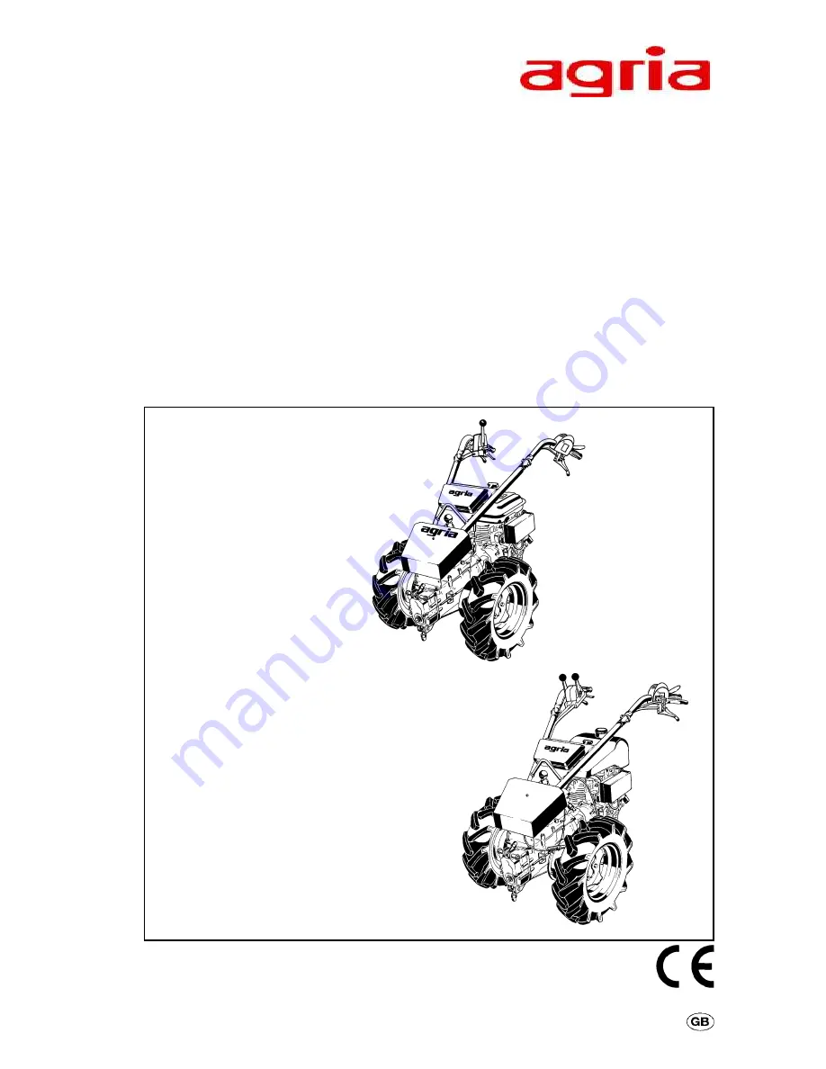
Page 1: ...2 Tool Carrier 5500 Grizzly compact comfort premium Operating Instructions Translation of the original operating instructions 4436 4672_1 compact Differential Safety hillholder Petrol engine EH 25 D comfort Differential Safety hillholder Petrol engine EH 34 D premium Steering brake clutch Brake central Petrol engine EH 25 D Petrol engine EH 34 D ...

Page 2: ...n sions stated in these instructions are not binding No claims can be derived from them We reserve the right for improvements without changing these instructions This delivery comprises l Operating instructions l Tool carrier l Tool kit Symbols Warning Danger Important information Choke Fuel Oil Glue Air filter Clutch Forward Reverse PTO Brake Parking brake Engine Start Engine Stop Engine oil leve...

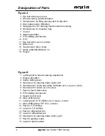
Page 3: ...agria Tool Carrier 5500 Grizzly 3 Designation of Parts Grizzly compact comfort with Differential Fig A Fig B Grizzly premium with Steering brake clutch Fig A Fig B ...

Page 4: ...o 18 Engine Figure B 1 Locking bolt for lateral steering adjustment 3 Engine off switch 4 Safety shifting lever 5 Hand lever for steering brake clutch left 6 Hand lever for clutch and safety hillholder Vers compact comfort 6 Hand lever for clutch Vers Premium 7 Pawl for hand clutch lever 8 PTO shifting mechanism 9 Speed control lever 10 Gear shifting lever 11 Locking lever for R shifting Vers comp...

Page 5: ...el Steering Brake Clutch26 Central Brake premium 26 Steering Handle 27 Loading Eye 27 Fixing Points 27 Drive Wheels 28 30 Wheel Weight 31 Hood 31 Coupling and Decoupling Attachments 32 4 Commissioning and Operation Commissioning the Machine 33 Starting the Petrol Engine 34 Switching off the Petrol Engine 35 Mowing 36 Danger Zone 37 5 Maintenance Petrol Engine 38 42 Air Filter 39 Spark Plug 41 Mach...

Page 6: ...tly using com mercially available lead free Normal and Super petrol also E10 as well as Super plus and Aspen 4T petrol Do not add oil to petrol If for environmental reasons you use unleaded petrol make sure the fuel is drained completely when shutting down the engine for more than 30 days This is to prevent resin residue from depos iting in the caburetor fuel filter and tank Or add a fuel stabiliz...

Page 7: ...ludes compliance with manufacturer s instructions on opera tion maintenance and repair Any unauthorized changes to the ma chine render manufacturer liability null and void General Instructions on Safety and Accident Prevention Basic Rule The standard accident prevention regu lations must be adhered to as well as all other generally accepted rules gov erning operational safety occupational health a...

Page 8: ... During opera tion always watch out for further objects and remove them in time For operation in enclosed areas ensure that a safety distance is kept to enclo sures to prevent damage to tools Operation and Safety Devices Before you start the engine Become familiar with the devices and operating elements and their functions Above all learn how to turn the engine off quickly and safely in an emergen...

Page 9: ...e the tool carrier turn off the engine Secure tool carrier against unauthorized use If machine is equipped with igni tion key remove the key For all other versions remove spark plug connector Implements Only mount implements with the engine and PTO switched off Always use appropriate tools and wear gloves when changing implements and parts thereof For mounting and dismounting imple ments bring sup...

Page 10: ...re you work on the engine always remove spark plug connector petrol engine only Check regularly and if necessary re place all protecting devices and tools subject to wear and tear Replace damaged cutting tools Always wear safety gloves and use proper tools when exchanging cutting tools Do not carry out repairs like welding grinding drilling etc on structural and safety relevant parts e g coupling ...

Page 11: ... stabi lizing liquids out of reach of children If sickness and vomiting occur see a doc tor If fuel has contacted eyes rinse them thoroughly avoid inhaling of va pours Read and observe enclosed instruc tions Before you dispose of opened and seemingly empty pressurised tins e g of assist starting liquids make sure they are completely empty Empty them in ventilated places safe from spark for mation ...

Page 12: ...rotective covers mounted Before starting the engine bring covers in proper position With engine run ning keep at a safe distance from cut ting knife Do not touch mov ing machinery parts Wait until they have come to a complete stop With engine run ning keep at a safe distance from tool carrier Signs When working with the ma chine wear individual protec tive ear plugs Wear protective gloves Wear sol...

Page 13: ... 255 270 ca 920 1270 20x8 00 10 560 740 255 270 ca 920 1270 21x11 00 8 560 740 260 270 ca 930 1270 EH 25 D EH 34 D m m Tool Carrier Dimensions Tyres 5 00 10 field tyre Optionally 3490 511 20x 8 00 10 grass tyre 3490 611 21x11 00 8 terra tyre Drive wheel attachment and applica tion see page 28 30 Tyre air pressure at 5 00 10 4 50 10 1 5 bar 21x11 00 8 0 8 bar 20x8 00 10 0 8 bar 3221 051 Pair wheel ...

Page 14: ...110kg Tool Carrier Grizzly comfort Type 5500 421 422 Engine 4 stroke petrol EH 34D Gearbox Mechanical gearbox 4 forward and 4 reverse speeds lockable differential Safety hillholder Transmission oil filling quantity approx 2 0 Ltr Transmission oil SAE 90 API GL5 e g BP Energear Hypo Travel Speeds km h PTO 825 rpm gear independent at engine speed 3600 rpm direction of rotation clockwise looking on P...

Page 15: ...490 360 560 430 300 710 580 450 680 550 420 830 700 570 740 610 480 890 760 630 6 20x8 00 10 R 560 370 180 650 460 270 650 460 270 740 550 360 770 580 390 860 670 480 830 640 450 920 730 540 7 5 00 12 AS 480 325 170 660 505 350 570 415 260 750 595 440 690 535 380 870 715 560 750 595 440 930 775 620 8 23x8 50 12 AS 520 305 90 740 525 310 610 395 180 830 615 400 730 515 300 950 735 520 790 575 360 1...

Page 16: ...king on PTO constant in forward and reverse Steering handle Anti vibration steering handle bearing 2 axle steering handle bearing Licenser is Frauenhofer Gesellschaft zur Förderung der angewandten Forschung e V German society for the promotion of applied research height adjustable side adjustable without tools Vibration acceleration value on handlebar grip Double knife mowing drive ahw 6 1 m s2 in...

Page 17: ... 420 660 490 320 880 710 540 720 550 380 940 770 600 1200 1080 420 1220 420 8 3 21x11 00 8 Terra 780 505 230 830 555 280 900 625 350 890 615 340 960 685 410 1220 230 10 1884 410 10 4 4 50 10 AS 670 550 430 640 520 400 790 670 550 700 580 460 850 730 610 1110 430 1154 430 10 1154 5 5 00 10 AS 680 550 420 650 520 390 800 670 540 710 580 450 860 730 600 1120 420 1164 420 10 1164 6 20x8 00 10 R 710 52...

Page 18: ...H 25D Air filter Dry filter element with foamed preliminary filter Carburetor Horizontal float carburetor Mixture control screw Basic setting 1 4 revs open Rated speed 3600 rpm Top no load speed 4000 rpm Idling speed 1200 rpm Engine oil Filling quantity approx 0 65 l Multi grade oil at ambient temperature 15 to 45 C SAE 10W 40 API SC or higher at ambient temperature 25 to 15 C SAE 5W 20 API SC or ...

Page 19: ...ium approx 8 l Air filter Dry filter element with foamed preliminary filter Carburetor Horizontal float carburetor Main jet 97 5 Idle jet 40 Mixture control screw Basic setting 7 8 revs open Rated speed 3600 rpm Top no load speed 4000 rpm Idling speed 1400 rpm Engine oil Filling quantity approx 1 2 l Multi grade oil at ambient temperature 15 to 45 C SAE 10W 40 API SC or higher at ambient temperatu...

Page 20: ...e necessary check ups done by an expert only During the first 20 operating hours break in period do not use engine to maximum power Even after break in period never use engine at higher speed than necessary for the work in hand I High engine speed is harmful to any engine and consider ably affects its durability This applies especially for no load operation Any overspeed have the engine roar can r...

Page 21: ...tch To turn engine off quickly bring switch into position 0 Safety Circuit Stop position Upon release of safety shifting lever B 4 the ignition system is switched off engine is off Caution engine continues running due to centrifugal mass Start position For starting the en gine and for short breaks press the safety shifting lever pull the hand clutch lever B 6 and lock with pawl B 7 Operating posit...

Page 22: ...d by further pulling the hand lever up wards Clutch Grizzly premium The machine is equipped with a single plate dry clutch Operation is via the hand clutch lever B 6 The machine is decoupled when you pull the hand clutch lever to po sition 0 Now the engine stops driv ing the tool carrier B 6 B 7 B 6 B 7 47 l To avoid clutch slipping away during operation a clutch play is factory set on the hand le...

Page 23: ... in neutral I In F R neutral the machine can be pushed Gear Shifting The gears 1 2 3 4 are engaged with the shifting lever B 10 Thereisnoneutralpositionbetweenthesegears I In general you can only drive the tool carrier if F R change is either in forward or reverse no matter whether gear is enganged or not PTO Shifting The gear independent PTO A 10 cannot be disconnected from the tool carrier will ...

Page 24: ...h the shifting lever B 10 There is no neutral position between these gears I In general you can only drive the tool carrier if F R change is either in forward or reverse no matter whether gear is enganged or not PTO Shifting The gear independent PTO A 10 cannot be disconnected from the tool carrier will always rotate with running engine The PTO shifting mechanism is arranged at the PTO shaft drive...

Page 25: ...aged differ ential I Because of the tractor s easy steering the differential should be unlocked when driving with the trailer mounted especially in curves Keep differential locked only as long as necessary Engaging the Differential Lock rigid wheel shaft On the move l Release throttle l Pull lever for differential lock slightly B 15 l Unlock pawl B 14 l Slowly release lever while pressing the thro...

Page 26: ... turns right To turn left pull hand lever B 5 W When turning on banks al ways turn the machine to wards the slope Central Brake To slow down or park the machine on hilly ground use the combined central hand brake l l l l l Central Brake Pull hand lever B 18 brakes act on both drive wheels Release hand lever and the lever swiv els back to original position brake is released l Hand Brake Pull hand l...

Page 27: ...d by about 30 to the left or right l l l l l Pull ball handle B 1 upwards and keep it in position then turn steering handle to the left or right into the desired positon l l l l l Release ball handle and slightly move steering handle to the left and right until the fixing bolt is engaged Eyelet for Loading The hooked yoke A 6 is meant for loading the machine and for suspending the retaining rope f...

Page 28: ...ts in each maintenance Snow Chains When working with snow chains fitted on wheels observe manufacturer s in structions make sure there is sufficient clearance between chains and machine parts Drive Wheels For full tractive power mount wheels with pointed parts of lugs showing in travel direction wheels seen from above Fit the countersunk side of spring lock washer into countersink type holes of di...

Page 29: ...31 Grizzly compact comfort Spring lock washer 100 Nm I For mowing on extremely steep slopes we recommend using twin wheels wheel centres or strake wheels Strake Wheels Item 5517 521 for drive wheels 5 00 10 Order of mounting Please note Wheel attachment bolt version B must be fit Fit spring lock washers between wheel bowl and flanges centring Make sure that wheel carriers point to machine when loo...

Page 30: ... washers between the wheel bowl and track width adjuster centering Lubrication Lubricate the wheel flange lube nipple at intervals of 100 operat ing hours or after cleaning with a pressure washer Use a grease gun Bio lubrication grease Adjustment of the differential hub The differential hubs are factory set to differential effect mount ing of rigid position see fig 3 Devices and Operating Elements...

Page 31: ... AS 4 50 50 AS Grizzly compact comfort Attach the weights to the wheels with the hex head bolts hex nuts and ser rated washers Tighten the hex nuts well Hood Remove Hood l Lift rear end of hood l Lift front end of hood and com pletely remove it Placing Hood l Place front and rear of hood with the rubber cups onto the ball heads l By slightly applying pressure to the rear and front of the engine co...

Page 32: ...O driven attach ment move lever 4 on the attachment to position 0 Coupling sleeve should slightly be greased with Bio lubrication grease Slide pegs 2 of basic ma chine into hooks 3 of attach ment Fold both eye bolts 1 over coupling flange Note l Make sure flanges 5 are properly centred and flat fit ted l Tighten cap nuts evenly For PTO driven attach ment press link 6 onto shift lever 4 until it lo...

Page 33: ... or fuel cans not suited for petrol are not permitted For the first commissioning or after longer periods of no operation fill fuel tank to maximum to avoid starting problems Be careful when dealing with fuel Fuel is easily inflammable and explosive in certain conditions l Do not refill in closed rooms l Before each fuel fill shut off the engine and wait until it has cooled off l Never refill clos...

Page 34: ...l Warm engine leave CHOKE knob in normal operating position or pull out half way Set ON OFF switch B 3 to operat ing position Set speed control lever B 9 to 1 3 throttle Pull hand clutch lever B 4 and lock pawl B 7 Pull starting rope on handle C 6or D 6 until you feel starter clutch engage Then pull hard and fast to start the engine After the start carefully let rope glide back Do not let snap Onc...

Page 35: ...ol carrier against unauthor ized use disconnect spark plug con nector I Engine off switch B 1 also serves as emergency off switch If necessary set switch to 0 to turn en gine off I For parking the machine for longer periods of no operation do not use engine off switch to turn off engine but close fuel taps and let en gine run until it slowly comes to a com plete stop This ensures carburetor to be ...

Page 36: ...e the brake Slowly release the hand clutch lever while pressing the throttle Caution with hot engine parts The exhaust and other engine parts become very hot if the engine runs and immediately after turning off Hold for sufficient distance from hot surfaces and keep children away from the running engine For direction change from forward to reverse proceed as follows Set speed control lever to idli...

Page 37: ...sure it is secured by another per son using a bar or a rope This per son must stay at a higher position than the vehicle and at a safe dis tance from the attachment at work If possible always work across the slope Starting the Engine on Slopes Keep the mowing drive and travel ling drive in engaged mode braking effect Move the hand clutch lever and safety shifting lever to Start position Start engi...

Page 38: ...an oil plug and surrounding parts l Remove oil plug clean dipstick with a clean cloth and dip back into oil tank do not screw in take out dipstick and read oil level l In case oil level is below lower mark min refill engine oil refer to Specifi cations until oil level reaches rim of oil filler neck max Changing Engine Oil The first oil change is after 25 oper ating hours Following oil changes are ...

Page 39: ...ap Carefully remove the foamed preliminary filter Wash the foamed prelimi nary filter in warm lye do not use petrol Sqeeze the foamed preliminary filter like a sponge and dry it Remove the filter element Tap the filter element against a smooth surface Do not clean the foamed pre liminary filter and the filter ele ment using compressed air and do not soak it in oil Reinstall the filter element and ...

Page 40: ... both serving for good air cir culation è Serviceç Exhaust Regularly clean surrounding parts of muffler C 9 or D 9 Free from grass dirt and inflammable deposits Danger of fire Fuel Hoses Exchange after every 2 years Ex change leaking fuel hoses immediately Cleaning the Fuel Strainer Check the strainer on the fuel tap C 3 at least once a year for water and other impurities l Close the fuel tap l Re...

Page 41: ...oosen the 4 fastening nuts 4 on the tank console and open approx 2 turn Slide fuel tank to the air filter side Slide back Slide tank back to exhaust side Tighten fastening nuts After every 100 operating hours or igni tion problems l Clean the electrodes on the spark plug from dust and dirt using a wire brush l Check spark plug gap and if neces sary readjust it to 0 6 0 7 mm Exchange the spark plug...

Page 42: ...ed At low speeds the engine is supposed to continue running smoothly when the speed control lever is at a stop in idling Adjust the engine speed while the en gine is still warm from operation For this purpose readjust the limiter screw 2 and the mix control screw 1 for idling speed Then turn the attachment or ad justing screw to adjust the throttle ca ble for no play For idling speeds refer to Spe...

Page 43: ... Clean the oil filler plug A 10 and the drain plug A 13 as well as the surrounding parts Change oil collect the old oil in a proper container and dispose of properly I Check and exchange o rings if necessary Tighten the drain plug For filling quantity and oil quality refer to Specifications Drive wheels l When commissioning the mower and each time you change wheels check and tighten wheel bolts an...

Page 44: ...0 operating hours Steering Handle Pendulum Stop This steering handle bearing provides optimum dampening when the two stop buffers are adjusted to a play of A 0 5 mm in position zero with no load on steering handle between stop plate and buffers However the pendulum stop can also be set to provide a rigid steering handle without play Adjustment Loosen hexagonal nuts 2 Adjust stop buffer 1 by turnin...

Page 45: ...g handle and place aside l Loosen lock nut 4 l Tighten adjustment nut 3 with 100 Nm l Re tighten lock nut 4 lock l Mount steering handle Brush some lubrication grease onto gliding faces if necessary l Screw on fastening nut 5 until steer ing handle is without play but can still be swivelled Secure with pin Steering Handle Pendulum Stop This 2 axle steering handle bearing provides optimum dampening...

Page 46: ...e must automatically come to a stop l Check electric conductors and con nections for good condition exchange if necessary è Serviceç 5 Maintenance B 4 6 6 6 6 6 A 6 6 6 6 6 A STOP Engine Off Switch Check engine off switch for proper func tion each time you do maintenance work on the machine l With the engine off switch in position 0 the engine must come to a stop l Check electric conductors and co...

Page 47: ...must be placed inthehand lever support on bottom position Diffential gear Central brake Steering brake X 3 5 mm The Bowden cable must be placed inthehand lever support on bottom position Hand lever for F R shifting Adjust Bowden cable in such a way that trans mission is set to neutral when pawl is locked The Bowden cable must be placed inthehand lever support on bottom position Adjustment 1 Remove...

Page 48: ...essary Check the brake free wheel l F R shifter on idle l Clutch on 0 l The brake disc must turn easily by hand readjust if necessary Check brake lining Every 100 operating hours check the brake linings 4 5 on wear and tear visual check The linings should have a min thickness of 3 mm replace the linings if necessary Replace brake lining l Loosen and unscrew the hex head nut 1 on both sides l Dismo...

Page 49: ...bricating grease or Bio lubricating oil e g speed control lever handle bearing etc Cleaning Engine Clean engine only with a cloth Avoid spray ing with water jets as water might penetrate into ignition and fuel system and cause mal functions Machine After each cleaning spraying with water expecially with air compressed water jets lubricate all lubrication points oil and let tool carrier run for a s...

Page 50: ...ression using the recoil starter Pull the starter rope until you feel resistance the valves are closed l Crank the engine slowly at 2 3 week intervals spark plug connector is re moved and set the valves on compres sion again d Drive wheels Support drive wheels in such a way that tyres have no ground contact Pneumatic tyres are quickly destroyed if left standing under load and uninflated e Clutch A...

Page 51: ... Tool Carrier 5500 Grizzly 51 Safety Circuit 1 Engine 2 Magnet ignition system 3 Engine off switch 4 Switch in clutch lever 5 Switch in safety lever Electric Circuit Electric Circuit bl blue br brown rt red ...

Page 52: ...or Tighten fastening screws and suction line Misfirings in Engine running in CHOKE range Set CHOKE lever to engine operating position 34 Loose ignition cable Fix ignition cable retaining device fit connector tightly on ignition cable fit connector tightly ojn spark plug Clogged fuel line or poor fuel Clean fuel line fill fresh fuel 40 33 Vent opening in fuel tank cap clogged Exchange fuel tank cap...

Page 53: ...when set to stop Engine Air filter clogged Clean air filter 39 output too low Loose cylinder head or Tighten cylinder head damaged sealing exchange sealing poor compression Have engine checked Machine in General Clutch does Hand clutch lever misadjusted Adjust clutch free play 47 not decouple Clutch slips Hand clutch lever misadjusted Adjust clutch free play 47 Worn out clutch Exchange clutch disc...

Page 54: ...ml 559 96 Glue ultra strong LOCTITE 638 bottle 50 ml 559 97 Surface sealing liquid LOCTITE 573 tube 250 ml Wear Parts Engine 707 91 Air filter set paper element preliminary filter 671 87 Spark plug Bosch WR7AC for EH 25D 707 92 Spark plug Bosch WR7CC for EH 34D 684 16 Sealing washer engine oil dip stick 009 05 Sealing washer 14 x 20 x 1 5 engine oil drain screw Transmission 009 16 Sealing washer 1...

Page 55: ...k cap 2 Fuel tank 3 Fuel tap 4 Air filter 5 Choke pull out knob 6 Starter handle 7 Recoil starter cooling air screen 8 Spark plug 9 Exhaust 10 Engine oil filler neck with oil dip stick 11 Engine type no 12 Engine oil drain plug 13 Engine ID no 14 Speed control lever and linkages Designation of Parts Petrol Engine ...

Page 56: ...56 agria Tool Carrier 5500 Grizzly Designation of Parts Petrol Engine Fig C Grizzly compact Grizzly comfort Grizzly premium Motor EH 34 Engine EH 25 D ...

Page 57: ...rier 5500 Grizzly 57 Lubrication Plan 1 2 4 3 5 6 6 6 6 6 6 B 6 6 6 6 6 8 h 6 6 6 6 6 50 h 25h 6 6 6 6 6 B yearly and always after cleaning with a high pressure cleaner 6 6 6 6 6 200 h 50 h 6 6 6 6 6 25 h 6 6 6 6 6 B ...

Page 58: ...l refill if necessary 1 K K 38 Check transmission oil level 3 K K 43 Tighten wheel bolts and nuts K 43 Retighten hex nuts for wheel flanges K K 43 Tighten steering handle central clamping W W 44 45 Cleaning K 49 First engine oil change 2 W 38 subsequent oil changes 2 W 38 Clean air filter insert W W 39 Lubricate all sliding parts 6 K K K 49 First transmission oil change 4 W 43 subsequent oil chang...

Page 59: ...tap 4 Air filter 5 Choke pull out knob 6 Starter handle 7 Recoil starter cooling air screen 8 Spark plug 9 Exhaust 10 Engine oil filler neck with oil dip stick 11 Engine type no 12 Engine oil drain plug 13 Engine ID no 14 Speed control lever and linkages 15 Fuel tap Designation of Parts Petrol Engine ...

Page 60: ...60 agria Tool Carrier 5500 Grizzly Fig D Grizzly premium Motor EH 34 D Designation of Parts Petrol Engine ...

Page 61: ...agria Tool Carrier 5500 Grizzly 61 Declaration Conformity ...

Page 62: ...Agria Werke GmbH Bittelbronner Straße 42 D 74219 Möckmühl Tel 49 6298 39 0 Fax 49 6298 39 111 e mail info agria de Internet www agria de Your local agria specialist dealer ...

Reviews: