19/09/18
Page 44 of 67
ASR650 Operational Manual
4.7.3
Tuning Data
As already mentioned in this manual earlier, the correct tuning of the antenna significantly decides
about the reading performance. The section
‘
Tuning Data
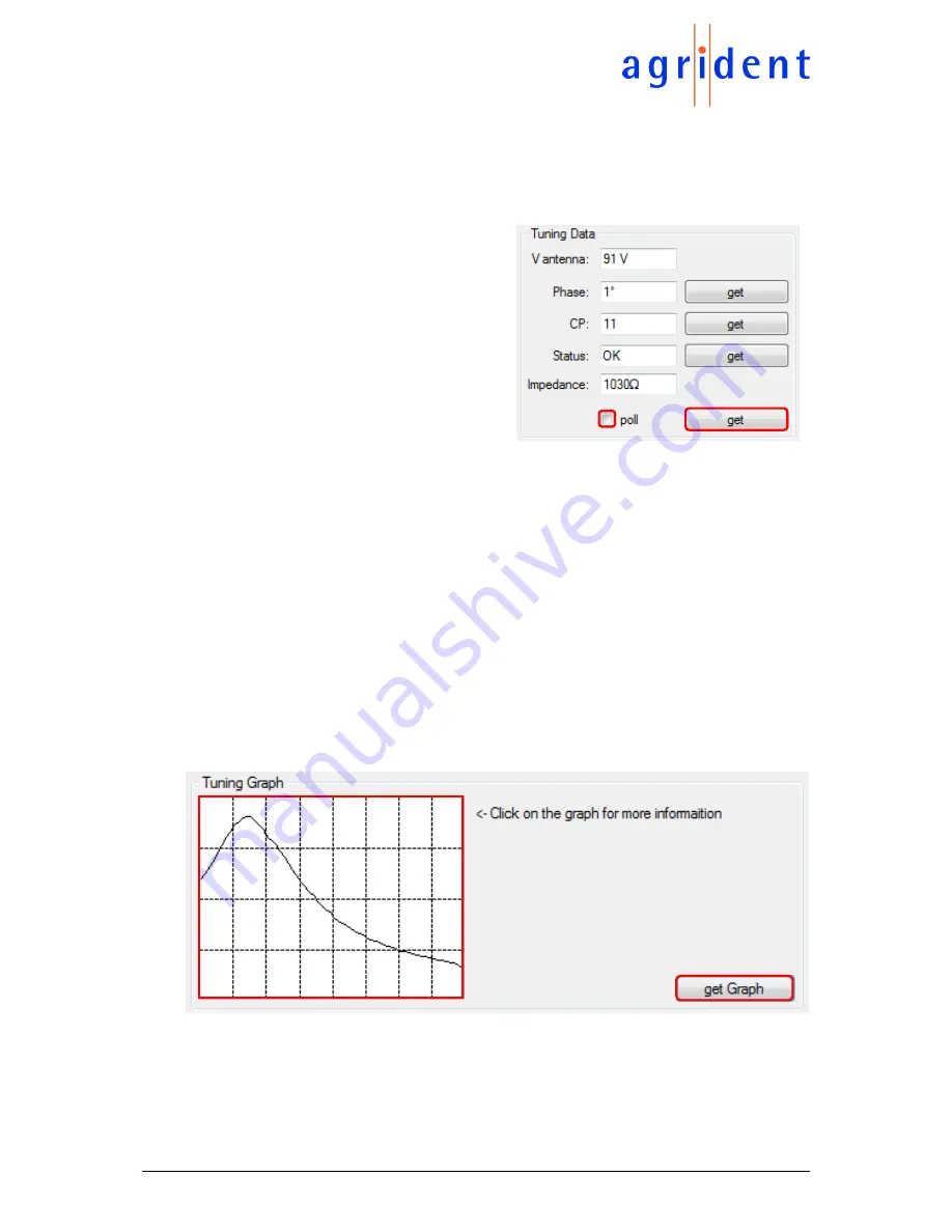
’ gives an overview about important
values concerning the antenna status.
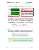
The antenna voltage
‘
V antenna
’ depends on
the selected transmit power level and the
antenna impedance. At maximum power the
voltage can be up to 100V. The Phase is only
used for internal purposes, so please don’t
care about this value.
‘
CP
’ indicates the
currently used
‘
Capacitor Pattern
’ or tuning
value. It should have a value of 9 to 11 ideally.
In case of having metal close to the antenna,
the value will increase since the reader has to
compensate
the
decreased
antenna
inductance by setting more tuning capacitors.
The
‘
Status
’ field gives further information in
case of an antenna fault. In this example it
says
‘
OK
’ because there is no antenna fault.
The antenna impedance is a very important
value. If this is too low for the selected power
level, the reader will disable the antenna.
Please also refer to chapter 2.1.6.
You might request these values once by pressing the ‘
get
’ button, or repeatedly by activating the
‘
poll
’ checkbox. When polling the status, the values will be updated about every second.
4.7.4
Tuning Graph
The
‘
Tuning Graph
’ section allows to request a complete tuning curve from the reader in one step
by clicking on the button ‘
get Graph
’. What the ASR is doing in this case is trying all 64 possible
Autotuning combinations while measuring the antenna voltage. The result is a curve indicating
where the voltage maximum is located.
If you click on any position within the graph drawing area, an additional window will open.

