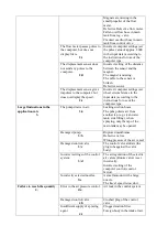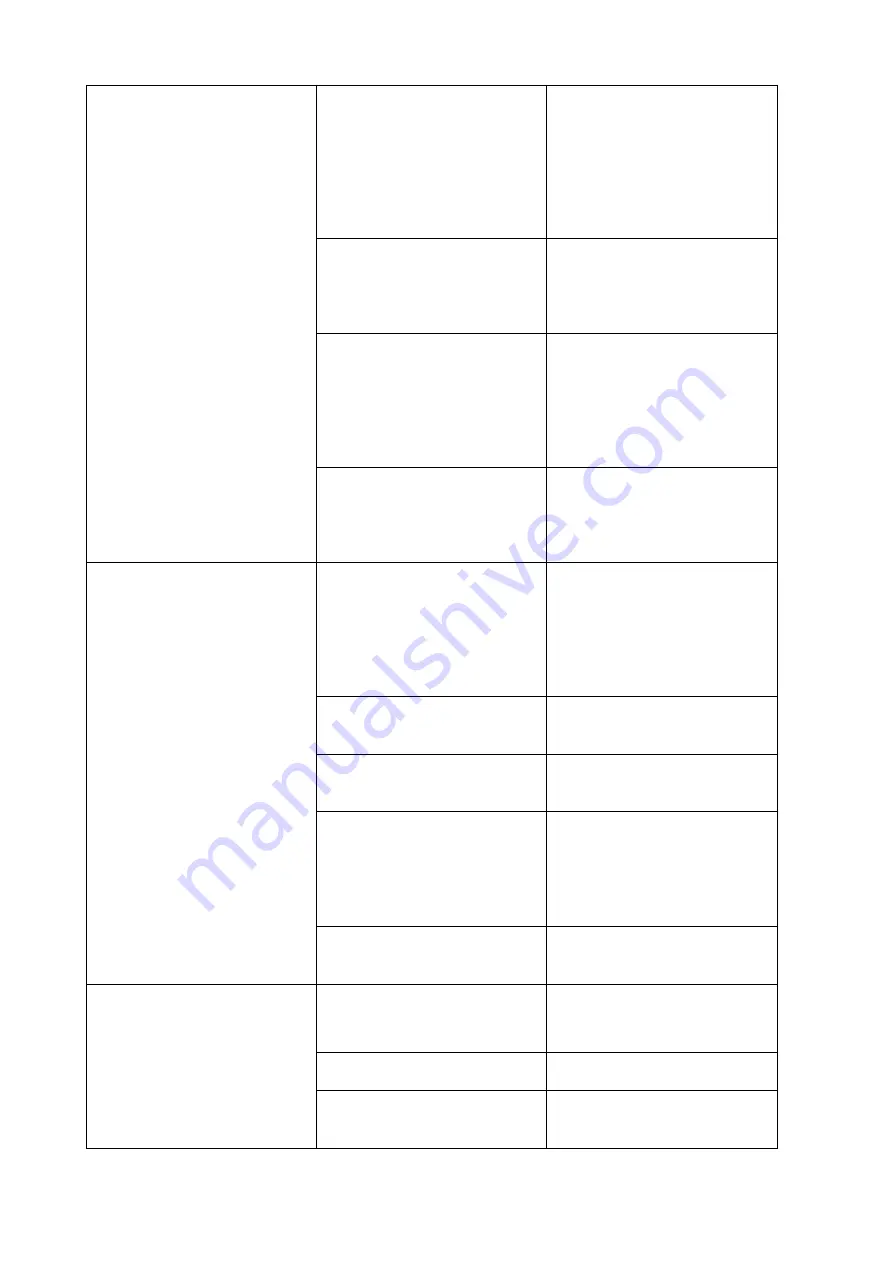
Magnets are missing in the
small propeller of the flow
meter.
Defective Defective flow meter.
Fallen overflow hose in main
tank from reg. valve.
Cracked overflow hose in main
tank from control valve.
The flow meter passes pulses to
the computer, but does not
display liters.
2/c
Incorrect computer settings (set
the pulse value of approx. 2000
in the input data) according to
the instructions for use of the
computer type.
The displacement sensor does
not send any pulses to the
computer.
2/d
Incorrect setting of the distance
between the sensor and the
magnet.
The magnet is missing.
The cable to the sensor is
broken.
Defective sensor.
The displacement sensor gives
impulses to the computer, but
does not display the speed.
2/e
Incorrect computer settings (set
wheel circumference in the
input data) according to the
instructions for use of the
computer type.
Large fluctuations in the
application rate
3.
The pump draws in air.
3/a
Leaking suction hoses.
The pump draws air from
another tap (e.g. clean water
tank, side filling), when
spraying, only the tap of the
main tank may be opened.
Damaged pump.
3/b
Ruptured membranes.
Defective valves.
Wrong pressure of the air vessel
Damaged control valve
3/c
The control valve stutters (the
plug rubs against the valve
body)
Incorrect settings of the control
system.
3/d
The air regulation of the electric
air valves (Kunke valve) is set
incorrectly.
Incorrect setting of the
computer control (control
factor).
Incorrectly selected nozzles.
3/e
A small amount with a large
nozzle.
The travel speed is too slow.
Failure to reach the quantity
4.
Error in the air pressure control.
4/a
Air leak in the control system
Damaged control valve
4/b
Crushed plug of the control
valve.
Insufficient supply of spraying
agent
4/c
Clogged suction filter.
Foreign body in the intake tract.
Summary of Contents for Gigant
Page 1: ...Instruction manual GIGANT ver 1 2022 ...
Page 16: ...4 3 1 Location of the safety labels BZ 3 BZ 3 BZ 3 BZ 4 BZ14 BZ 5 BZ 7 BZ 8 BZ 9 BZ 6 ...
Page 66: ......
Page 78: ......
Page 82: ......
Page 88: ...19Attachments 19 1 Hydraulic diagram of the sprayer ...
Page 89: ...19 2 Sprayer water scheme ...


