background image

User manual - Maximulch - Series 3 | Series 5 | Series 6

Operation

72

NOTT-GB-708-A

06/12/2019

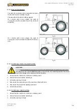
An identical setting must be used to each of the blades.

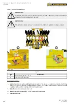
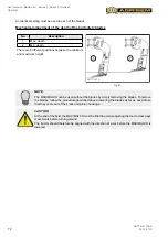
Mechanical adjustment of the depth of the bolt safety blades

No.

Description

1

Max. depth

2

Min. depth

There are 6 different positions between the minimum 

and maximum height.

1

2

NOTT-0422

Fig. 61


NOTE

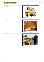
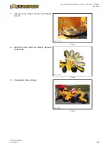
The MAXIMULCH can be used without the blades by simply removing the blades. To remove 

the blades, follow the procedure described above, lowering the blades as far as possible so 

that they come out of their rack and pinion housings.

CAUTION

At the end of the field, the MAXIMULCH must be lifted to avoid subjecting the tool to crossways 

movements before turning around.
The tractor should therefore be aligned with the direction of work before the MAXIMULCH is 

lowered.

Summary of Contents for 5 Series

Page 1: ...ultivators Maximulch Series 3 Series 5 Series 6 NOTT GB 708 A 06 12 2019 EN Manual translated from French AGRISEM INTERNATIONAL S A 535 Rue Pierre Levasseur CS 60263 44158 ANCENIS FRANCE Tel 33 0 2 51 14 14 40 Fax 33 0 2 40 96 32 36 ...

Page 2: ......

Page 3: ...on of data plate 17 3 3 Identification of the machine 21 4 Warranty 22 4 1 Warranty conditions 22 4 2 Exclusive liability clause 25 5 Safety instructions 26 5 1 Safety instructions 26 5 2 Safety symbols on the machine 40 6 Operation 48 6 1 Location and description of controls 48 6 2 Start up 56 6 3 Hitching unhitching 56 6 4 Folding unfolding 60 6 5 When driving on the road 68 6 6 Dual line air br...

Page 4: ...recommendations 83 6 18 Immobilising the tractor machine 83 7 Winter Storage Handling Transport 85 7 1 Storage 85 7 2 Handling 86 7 3 Transport 91 8 Servicing Maintenance 96 8 1 Maintenance tips 96 8 2 Maintenance consumables 100 8 3 Maintenance schedule 100 8 4 Maintenance operations 101 9 Faults causes and remedies 117 10 Characteristics 118 10 1 Series 3 118 10 2 Series 5 119 10 3 Series 6 120 ...

Page 5: ...f your new equipment Please read it and ensure that all users scrupulously follow the instructions contained The following pages provide essential information on your machine read them carefully Your AGRISEM INTERNATIONAL dealer will provide high quality servicing as well as any assistance you may require For servicing remember that your dealer is the person who is most familiar with your machine ...

Page 6: ...ver all eventualities The user must comply with the applicable legislation in particular with regard to safety ensure that the rules of safety and caution dictated by the situation are applied use common sense and adapt the use of the machine to the circumstances It is the Purchaser s responsibility to check that the AGRISEM INTERNATIONAL machine complies with the legislation and regulations appli...

Page 7: ...n NOTT User manual FR GB DE PL RU French English German Polish Russian 705 Type of machine A Version of the manual 1 5 Description of warning terms DANGER This pictogram indicates a hazardous situation for the user Consequences death or serious injury are inevitable WARNING This pictogram indicates a hazardous situation for the user Consequences death or serious injury may occur CAUTION This picto...

Page 8: ...posed of in a conventional dustbin but collected through special channels MOEBIUS LOOP The universal recycling symbol It indicates that the product or its packaging is technically recyclable not that it is or will be recycled The products will only be recycled under two conditions the sorting and recycling channel exists in your region the products have been correctly sorted ...

Page 9: ...sks Correct use implies strictly adhering to the instruction given in the user manual as well as the operating servicing and repair rules defined by the manufacturer The user and the owner are responsible for complying with the specific accident prevention instructions and well as the general rules relating to safety occupational medicine and highway legislation Any use other than that defined abo...

Page 10: ... Ø 80 optional SRE Ø 100 SRE Ø 100 SRE Ø 100 NOTT 0033 Disc size mm Ø 560 Ø 560 optional Ø 610 Ø 560 optional Ø 610 Ø 610 Ø 610 NOTT 0413 Working depth cm 25 30 25 40 30 NOTT 0035 Distance between elements mm Distance between disc support beams 1520 mm 250 mm pitch row of tines in the middle Distance between disc support beams 1640 mm 290 mm pitch row of tines in the middle Distance between disc s...

Page 11: ...machine 11 NOTT GB 708 A 06 12 2019 2 2 2 Maximulch series 3 fixed tractor mounted NOTT 0384 1 2 3 4 5 6 7 8 Fig 1 No Description 1 Hitch 2 3D security 3 Multistop depth adjustment system 4 Blade security 5 Blades 6 Mulcher discs 7 Rollers 8 Signalling lights and panels ...

Page 12: ...sentation of the machine 12 NOTT GB 708 A 06 12 2019 2 2 3 Maximulch series 3 HD tractor mounted NOTT 0414 1 2 3 4 5 6 Fig 2 No Description 1 Hitch 2 3D security 3 Multistop depth adjustment system 4 Blades 5 Mulcher discs 6 Signalling lights and panels ...

Page 13: ...GB 708 A 06 12 2019 2 2 4 Maximulch series 3 folding trailed NOTT 0385 1 2 3 4 5 6 7 8 9 10 Fig 3 No Description 1 Hitch 2 3D security 3 Multistop depth adjustment system 4 Blade security 5 Blades 6 Mulcher discs 7 Rollers 8 Deflectors 9 Transport wheels 10 Signalling lights and panels ...

Page 14: ...Series 5 Series 6 Presentation of the machine 14 NOTT GB 708 A 06 12 2019 2 2 5 Maximulch series 5 fixed trailed NOTT 0386 1 2 3 4 5 6 Fig 4 No Description 1 Hitch 2 3D suspension 3 Blades 4 Mulcher discs 5 Rollers 6 Transport wheels ...

Page 15: ...Presentation of the machine 15 NOTT GB 708 A 06 12 2019 2 2 6 Maximulch series 5 folding trailed NOTT 0387 1 2 3 4 5 6 7 Fig 5 No Description 1 Hitch 2 3D suspension 3 Blades 4 Mulcher discs 5 Rollers 6 Transport wheels 7 Signalling lights and panels ...

Page 16: ... of the machine 16 NOTT GB 708 A 06 12 2019 2 2 7 Maximulch series 6 folding trailed NOTT 0388 1 2 3 4 5 6 7 8 Fig 6 No Description 1 Hitch 2 3D suspension 3 Blades 4 Mulcher discs 5 Rollers 6 Transport wheels 7 Signalling lights and panels 8 Parking support leg ...

Page 17: ...lch Series 5 folding trailed Maximulch Series 6 folding trailed IMPORTANT This user manual is published for wide circulation and the availability of the equipment indicated whether on the basic machine or as accessories may vary according to the region in which the machine is used All combinations available at the time of publishing the manual will be described therein 3 2 Location and description...

Page 18: ...ludes the following information No Description 1 Model 2 Serial or identification number 3 Year of manufacture 4 Empty weight of the equipment NOTT 0052 1 2 3 4 Fig 8 3 2 2 Trailed machines type approved for road use The data plate is located on the front frame Series 3 NOTT 0390 Fig 9 Series 5 NOTT 0391 Fig 10 ...

Page 19: ...2 Fig 11 The data plate includes the following information No Description 1 Make 2 Type variant version 3 Serial or identification number 4 Date of approval 5 Issuing authority DREAL 6 Gross vehicle weight 7 Unladen weight 8 Not used 9 Not used 10 Max weight on drawbar eye NOTT 0243 1 2 3 4 5 6 7 8 9 10 Fig 12 ...

Page 20: ... description section VDS code 2a Machine family 2b Type of brake 3 Vehicle identification section VIS code 3a Year of manufacture 3b Place of manufacture 3c Manufacturing number 3d Width of machine 3e Incrementation The example opposite is therefore the identification number of a Maximulch Series 3 trailed cultivator with hydraulic braking manufactured in 2018 by AGRISEM INTERNATIONAL and 4 5 m wi...

Page 21: ...ormation Fill in the column with the requested information Type of machine Serial number Year of manufacture Date of first use Name of the dealer Dealer s address Dealer s telephone number AGRISEM INTERNATIONAL S A 535 Rue Pierre Levasseur CS 60263 44158 ANCENIS France Tel 33 0 2 51 14 14 40 Fax 33 0 2 40 96 32 36 E mail agrisem agrisem com IMPORTANT This document should be kept inside this user m...

Page 22: ... Company s address for expert inspection AGRISEM INTERNATIONAL S A 535 Rue Pierre Levasseur CS 60263 44158 ANCENIS France Tel 33 0 2 51 14 14 40 Fax 33 0 2 40 96 32 36 The following shall be considered to constitute proof of the date of delivery of the equipment the date of the delivery note and the purchaser invoice date the return of the warranty certificate stamped and signed by the dealer and ...

Page 23: ...cified by AGRISEM INTERNATIONAL In the event of improper use of the machine Please refer to the chapter Intended use of the equipment page 9 regarding this point If the manufacturer s instructions and requirements given in this manual are not complied with particularly those regarding safety assembly start up use operation and servicing In the event of improper handling on the part of the user Cau...

Page 24: ...thout fail using anAGRISEM INTERNATIONAL WARRANTY CLAIM FORM see appendix and sent by registered letter with acknowledgement of receipt by the dealer to the company s technical department within 10 days of the incident This form must be completed legibly by the dealer and must include the following information Name and address of the dealer code No Name and address of the purchaser Type of machine...

Page 25: ...ctly installed or not working Combining of the machine with other instruments or machines without the written agreement of AGRISEM INTERNATIONAL and or without complying with the instructions given by the manufacturers of the tractor and the other instruments or machines Modifications made to the machine without the written permission of AGRISEM INTERNATIONAL Fitting of spare parts accessories or ...

Page 26: ...y be exposed This machine must only be used in accordance with its purpose and in a condition that does not present any safety risks Any malfunctions likely to be detrimental to safety must be corrected immediately The user is required to strictly adhere to the safety instructions in this manual and the stickers affixed to the machine The safety panels and guards have been omitted from some illust...

Page 27: ...heck the area around the machine no one must be within 50 metres of the machine Check that there is sufficient visibility to ensure this condition of use Before carrying out any work ensure that weight distribution on the tractor ensures a stable assembly The tractor must be sufficiently ballasted at the front to avoid any risk of the front lifting If not add weights to the front of the tractor Ch...

Page 28: ... contact the AGRISEM INTERNATIONAL customer service network Check that the tractor has the characteristics necessary to hitch the machine see Characteristics page 118 WARNING Use of a tractor that is non compliant with the machine to which it is attached will incur the following risks Coupling failure Instability under load Instability during manoeuvring Insufficient braking capacity Check that th...

Page 29: ...front ballast a m Distance between the centre of gravity of the front mounted machine or front ballast and the centre of the front axle sum of a1 a2 see technical characteristics of the tractor and the front mounted machine or front ballast or measurement a1 m Spacing between the centre of the front axle and the centre of lower arms hitch point see the tractor s user manual or measurement a2 m Dis...

Page 30: ...llast distance from the centre of gravity see technical characteristics of the machine Calculation of the required minimum ballasting at the front GV min of the tractor to ensure manoeuvrability Enter the value for the calculated minimum ballast GV min required on the front of the tractor in the table on page 31 NOTT 0223 Fig 15 Calculation of the actual front axle load of the tractor TV tat Enter...

Page 31: ...or the calculated actual rear axle load and the approved tractor rear axle load specified in the tractor user manual in the table page 31 NOTT 0226 Fig 18 Load capacities of the tyres Enter the double value two tyres of the permissible load capacity see for example the tyre manufacturer s documents and enter the result in the table on page 31 Table Actual value obtained by calculation Authorised v...

Page 32: ...g entanglement winding entrapment or impact may occur when working on the machine in the following cases accidental lowering of a non immobilised machine raising of the tractor s three point hitch via the hydraulic circuit accidental lowering of raised non immobilised components of the machine accidental start up and movement of the combined tractor machine Before carrying out any operations on th...

Page 33: ...have been exhausted the competent authority according to the law of the Land may issue a waiver based on the report of an approved expert in the field of motor vehicle circulation and with the agreement of the manufacturer in accordance with article 70 of the German law governing the authorisation of vehicles to use the public highway and the obligatory authorisation under the German highway code ...

Page 34: ...A 50 metre safety zone must be kept clear around the machine Move any people or animals likely to be in the danger area around the machine Do not stand in the machine s working area nor in the machine s rotation or swivel area Each time the machine is used carry out a careful visual inspection of the machine to detect any external damage and ensure the correct operation of safety and protection de...

Page 35: ... changes of position Also check that the screws nuts and bolts are tightened and that all of the machine parts are correctly attached and cannot move or become detached If the machine is a folding machine the locking system must be engaged Follow the instructions in this manual on how to prepare the machine for transport If necessary also check the connection of the supply pipes the braking system...

Page 36: ...fluids or inflammable products Instructions regarding installation The machine may be fitted with electronic components and elements which may be affected by electromagnetic emissions from other devices This type of interference may be a source of danger for people if the following safety instructions are not followed If electrical components and or devices are installed on the machine and connect...

Page 37: ...rectly or which leak Hydraulic hoses must never trail on the ground If a leak is detected take all of the necessary precautions to avoid accidents Never try to plug the leak with your hand or fingers Any pressurised liquid in particular oil in the hydraulic circuit can penetrate the skin and cause serious injury and infection In the event of injury seek immediate medical attention To avoid acciden...

Page 38: ...achines fitted with spring assembly safety systems Safety devices with pre compressed spring assemblies are fitted on many AGRISEM INTERNATIONAL tools These can be very dangerous when performing technical operations on the machine if all of the necessary precautions are not taken CAUTION Written authorisation must be obtained from AGRISEM INTERNATIONAL before carrying out any operations on the Spr...

Page 39: ...e machine and the official documents once handed over by the dealer To do this go to https my agrisem com and follow the instruction given on the web site 5 1 13 User s workstation The machine must be operated by one person only from the tractor driver s seat Before each use check the area around the machine no one must be within 50 metres of the machine Check that there is sufficient visibility t...

Page 40: ...fety programme Also study all the usual work protection measures and above all do not forget Safety depends on you You can avoid accidents causing serious injury or death No Reference Symbol Meaning 1 ETIQ01 603 WARNING DANGER Read the instruction manual and safety instructions before starting up the machine and abide by them during operation 2 ETIQ01 601 WARNING DANGER Stop the engine and remove ...

Page 41: ...ructions in the user manual 6 ETIQ01 609 RISK OF CRUSHING Do not remain in the working area to avoid any risk of crushing 7 ETIQ01 621 RISK OF TIPPING To avoid any risk of tipping do not unfold the equipment in steeply sloping areas 8 ETIQ01 625 RISK OF PINCHING Keep away from all moving parts to avoid any risk of pinching 9 ETIQ01 633 RISK OF CRUSHING CUTS Keep away from the machine to avoid the ...

Page 42: ...plements 11 ETIQ01 639 RISK OF EXPLOSION Pressure tank do not service or repair 12 ETIQ01 643 RISK OF ELECTROCUTION Risk of electrocution keep away from electric lines 13 ETIQ01 651 RISK OF FALLING Risk of falling do not transport anyone on the machine 14 ETIQ01 657 RISK OF LOOSENING Risk of loosening regularly check the tightness of the components in accordance with the maintenance plan ...

Page 43: ...Q01 607 RISK OF CRUSHING BETWEEN THE TRACTOR AND THE MACHINE Always remain outside the working area of the three point linkage when using remote control 17 ETIQ01 623 RISK OF CRUSHING 18 ETIQ01 649 RISK OF CRUSHING Never climb on the machine while the tractor engine is running IMPORTANT These safety symbols must be present on the machine and legible If any symbols are missing or damaged contact AG...

Page 44: ...User manual Maximulch Series 3 Series 5 Series 6 Safety instructions 44 NOTT GB 708 A 06 12 2019 5 2 1 Series 3 fixed tractor mounted NOTT 0395 5 3 13 2 14 16 1 15 8 9 10 18 10 18 15 9 8 Fig 19 ...

Page 45: ...imulch Series 3 Series 5 Series 6 Safety instructions 45 NOTT GB 708 A 06 12 2019 5 2 2 Series 3 folding trailed NOTT 0396 5 3 1 2 16 6 7 10 9 12 13 1 2 16 6 7 10 9 12 13 15 4 9 14 2 1 8 8 18 4 9 18 4 9 15 4 9 Fig 20 ...

Page 46: ...imulch Series 3 Series 5 Series 6 Safety instructions 46 NOTT GB 708 A 06 12 2019 5 2 3 Series 5 NOTT 0398 1 9 10 2 14 6 9 5 13 5 9 4 15 1 2 14 15 18 8 8 x4 1 2 14 6 9 5 13 1 2 14 3 9 10 15 18 5 9 4 15 8 5 3 3 Fig 21 ...

Page 47: ...ulch Series 3 Series 5 Series 6 Safety instructions 47 NOTT GB 708 A 06 12 2019 5 2 4 Series 6 NOTT 0399 1 9 4 2 16 6 7 10 9 12 9 4 15 1 2 14 18 8 8 x4 1 2 16 6 7 10 9 1 2 14 9 4 18 9 4 15 5 3 13 8 x4 8 12 13 8 8 Fig 22 ...

Page 48: ...2019 6 Operation 6 1 Location and description of controls 6 1 1 Tractor mounted machine coupling No Description 1 Top link coupling pin 2 Lower link coupling pin 3 Fixed top link pin position 4 Floating top link pin position 5 Fixed bottom link pin position NOTT 0415 5 2 1 4 3 Fig 23 ...

Page 49: ...eries 3 Series 5 Series 6 Operation 49 NOTT GB 708 A 06 12 2019 6 1 2 Trailed machine coupling No Description 1 Drawbar 2 Towing bracket 3 Drawbar coupling 4 Ball head drawbar coupling 5 Drawbar eye NOTT 0416 2 1 4 3 5 Fig 24 ...

Page 50: ...ach hydraulic line are indicated by colour codes on the hydraulic hoses and the following pictograms The pictograms are located on the drawbar coupling hose support bracket NOTE The pictograms are common to the entire AGRISEM INTERNATIONAL machine range certain functions may not be available on your machine NOTT 0250 Fig 25 No Description Hose colour code NOTT 0251 Raise Lower hydraulic drawbar Ye...

Page 51: ...Description Hose colour code NOTT 0254 Raise Lower axle Green NOTT 0255 Turbine Red NOTT 0256 Raise Lower markers Black NOTT 0259 Strength adjustment of crossboards Orange NOTT 0258 Depth adjustment of blades or tines Black NOTT 0257 Fold Unfold Blue NOTT 0260 Extend Retract extensions Black ...

Page 52: ...T GB 708 A 06 12 2019 No Description Hose colour code NOTT 0261 Depth adjustment of discs Orange NOTT 0262 Depth adjustment of tines Black NOTT 0263 Depth adjustment of coulters Orange NOTT 0264 Raise Lower seeding ramp Yellow NOTT 0265 Extend Retract extensions Blue ...

Page 53: ...atic connectors No Description 1 Yellow hand 2 Red hand NOTT 0329 1 2 Fig 26 6 1 5 Hydraulic control valves According to the model hydraulically controlled elements are isolated and controlled by means of valves Model Series 3 tractor mounted No Description 1 Folding roller NOTT 0417 1 ON OFF Fig 27 ...

Page 54: ...s 3 folding trailed No Description 1 Extension 2 Axle 3 Drawbar 4 Folding speed NOTT 0323 2 1 3 4 Fig 28 NOTT 0322 ON OFF ON OFF ON OFF 2 1 3 4 Fig 29 Models Series 5 trailed No Description 1 Axle 2 Drawbar 3 Depth of discs 4 Depth of rollers 5 Roller speed NOTT 0418 1 2 1 3 2 4 3 4 5 5 ON OFF Fig 30 ...

Page 55: ...odel Series 6 No Description 1 Drawbar 2 Depth of rollers or depth of levelling discs NOTT 0419 1 2 1 2 ON OFF Fig 31 6 1 6 Lighting system NOTT 0334 2 3 3 1 2 4 Fig 32 No Description Characteristics 1 Headlight 12 V 55 W 2 Indicator lamp 12 V 21 W 3 Brake light 12 V 21 W 4 Trailer socket ...

Page 56: ...ility of the tractor and the machine Front link arm of sufficient capacity Double acting hydraulic control valve Single hydraulic line connected to the pressure free return A 7 pin 12 V female connector for the tractor front lighting kit 6 3 Hitching unhitching CAUTION Always carry out hitching and unhitching operations carefully and smoothly without sudden movements CAUTION Before carrying out hi...

Page 57: ...e is room to pass under bridges and low power lines e g Maximulch 6 m CAUTION On tractor mounted machines the drawbar must be hitched to the top holes on the lower arms This improves the stability of the machine when working 6 3 2 Hitching a tractor mounted machine 1 Ensure that the machine is on stable ground 2 Bring the tractor up to the coupling on the machine 3 Align the lower link arms with t...

Page 58: ...ting equipment and check its operation 6 Remove the parking stands if the machine is fitted with them 7 Lift the machine with the drawbar and the trailed or semi mounted kit 8 Fold the side extensions for transport see Transport page 91 9 Lock the machine for transport if it folds using hydraulically controlled hooks or mechanical locks 10 Ensure that everything is correctly connected and locked a...

Page 59: ...tching a tractor mounted machine CAUTION For the Maximulch Series 3 tractor mounted model with the hydraulically folding roller option the roller must be in the WORKING position to prevent the tool swivelling towards the tractor due to the change in the machine s centre of gravity 1 Ensure that the machine is unhitched on stable ground 2 Unlock the machine before unfolding it 3 Unfold the machine ...

Page 60: ...dbrake system if fitted 8 Disconnect the plug for the lighting equipment 9 Unhitch the machine 6 4 Folding unfolding 6 4 1 Folding unfolding the roller WARNING Before carrying out hitching and unhitching operations you MUST refer to the safety instructions WARNING Before folding or unfolding check that there are no foreign bodies that could hinder movement WARNING No one must be within 50 metres o...

Page 61: ...es 6 Operation 61 NOTT GB 708 A 06 12 2019 2 Fold the roller using the tractor s hydraulic control valve NOTT 0268 Fig 37 3 Close the valve located under the hose support bracket NOTT 0269 Fig 38 4 Fold the border spreading disc NOTT 0270 Fig 39 ...

Page 62: ...al position roller folded NOTT 0271 Fig 40 6 4 3 Unfolding the hydraulic roller Operations must be performed in the order indicated below to avoid damaging certain components of the Maximulch 1 Initial position roller folded NOTT 0271 Fig 41 2 Unfold the border spreading disc NOTT 0270 Fig 42 ...

Page 63: ...es 6 Operation 63 NOTT GB 708 A 06 12 2019 3 Open the valve located under the hose support bracket NOTT 0272 Fig 43 4 Unfold the roller using the tractor s hydraulic control valve NOTT 0268 Fig 44 5 Final position roller unfolded NOTT 0267 Fig 45 ...

Page 64: ...ders are fully extended NOTT 0426 1 2 Fig 46 No Description 1 Deactivated hydraulic sensor 2 Activated hydraulic sensor Folding procedure 1 Actuate the roller arm cylinders to their maximum extent This allows the rollers to be retracted within the machine as much as possible in their transport position The rollers must therefore remain within the regulatory width width of less than 2 98 m during t...

Page 65: ...ly locking version manually install the locking bar IMPORTANT If the safety system is not engaged the tool cannot be unfolded NOTT 0276 Fig 48 6 When the extensions are locked activate the mechanical locking control valve locking catch 6 4 5 Unfolding the extensions Operations must be performed in the order indicated below to avoid damaging certain components of the Maximulch 1 Initial position ma...

Page 66: ...on for two part folding Maximulch versions see 6 9 1 Roller adjustment page 70 NOTT 0280 MULTISTOP Fig 50 3 Operate the system in the folding position until the folding system unlocks Hydraulic locking version the system unlocks automatically when pressurised Mechanical locking version manually remove the locking bar NOTT 0276 Fig 51 NOTT 0282 Fig 52 ...

Page 67: ...olding hydraulic control valve up to the mechanical stop point NOTT 0273 Fig 54 6 4 6 Extension folding unfolding end stop adjustment CAUTION The extensions of certain machines can be adjusted Regularly check that the machine remains level when working Adjust the stop screws to give the unit an upwardly curving shape when hitched and raised NOTT 0283 Fig 55 ...

Page 68: ...e machine must be converted to the transport position Raise the machine completely to prevent the working elements dragging on the ground Road transport speed should not exceed 25 kph 6 6 Dual line air brake system If the Maximulch is equipped with air brakes the yellow 1 and red 2 lines must be connected to the tractor for optimum braking NOTT 0329 1 2 Fig 57 ...

Page 69: ...he machine to the parking position 2 Chock the wheels 3 With the machine still connected to the tractor disconnect the red brake line then the yellow line 4 The brake is automatically actuated and the machine will not move NOTE If the machine s tank is drained of air once all lines have been detached the brakes will come off same situation as pushing the shunt valve 5 Put the hoses back in place 6...

Page 70: ...re secure braking of the towed unit in the event of a coupling failure Once the machine is immobilised manually operate the handbrake 6 9 Adjusting the working depth 6 9 1 Roller adjustment The working depth of the discs is affected by the roller setting The roller also serves to level and compress the soil after it has been loosened by the discs The roller setting is adjusted by means of the AGRI...

Page 71: ...esponds to the position in which the roller is the furthest away for greater distance between the roller kit and the rear row of discs Positions C and D correspond to the bottom roller stop This allows you to limit the travel of the roller arm between the lower and upper stops NOTT 0285 MULTISTOP a b Fig 60 NOTE A Maximulch works at shallow depth between 2 and 6 cm thanks to a high travel speed ap...

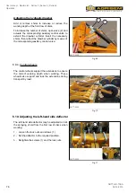
Page 72: ...aximum height 1 2 NOTT 0422 Fig 61 NOTE The MAXIMULCH can be used without the blades by simply removing the blades To remove the blades follow the procedure described above lowering the blades as far as possible so that they come out of their rack and pinion housings CAUTION At the end of the field the MAXIMULCH must be lifted to avoid subjecting the tool to crossways movements before turning arou...

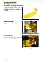
Page 73: ...des NOTT 0425 Fig 62 IMPORTANT Never remove the pin if the clip 1 is missing 1 Check that the beta clip 1 is present to prevent the blade falling when it is adjusted 2 Remove the pin 2 3 Using a wrench slide the blade to the required height by means of the screw 3 4 Once the blade is in position refit the pin 2 and its clip 1 2 3 NOTT 0421 Fig 63 ...

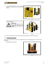
Page 74: ...he end of the field the MAXIMULCH must be lifted to avoid subjecting the tool to crossways movements before turning around The tractor should therefore be aligned with the direction of work before the MAXIMULCH is lowered Hydraulic adjustment of blade depth 1 Release the pressure on the pins by raising the blades slightly using the tractor s control valve 2 Remove the adjustment pins NOTT 0423 Fig...

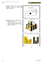
Page 75: ...rking depth on the 2 rows of discs Adjust the drawbar setting so that it is tilted slightly towards the ground NOTT 0420 Fig 66 In the ball hitch version on the tractor s lift arms the height of the linkage controls height of the first row of discs NOTT 0287 Fig 67 Adjusting the mechanical drawbar Tighten or loosen the mechanical drawbar to increase or reduce the working depth of the front row of ...

Page 76: ...ylinder by means of the corresponding auxiliary control valve NOTT 0289 1 2 Fig 69 6 9 4 Control wheels The control wheels support the extensions to ensure the correct working depth when working These wheels also support and lock the extensions during transport by road NOTT 0330 Fig 70 6 10 Adjusting the left hand side deflector The left hand side deflector may be adjusted to limit the spraying of...

Page 77: ...d to limit the spraying of soil from the second row of discs The deflector must not be in contact with the ground during use NOTT 0301 Fig 72 Adjustment of clearance Adjust the clearance between the last disc and the deflector NOTT 0294 Fig 73 Vertical adjustment This adjusts the clearance between the ground and the deflector by turning the stop screw 1 NOTT 0295 1 Fig 74 ...

Page 78: ...signed to break clods The adjustment of the board may be fine tuned according to the conditions of use 1 Remove the screws 2 at each end of the board 2 Set the deflector to the required position 3 Retighten the screws 2 NOTT 0296 1 2 Fig 75 6 13 Adjusting the border spreading disc For Maximulch Series 3 machines only The machine can be fitted with a border spreading disc to prevent a ridge forming...

Page 79: ...r spreading disc is adjusted by means of screws 1 NOTT 0298 1 Fig 78 The border spreading disc is adjusted by means of screws 1 NOTT 0299 1 Fig 79 When the machine is equipped with a folding roller adjustments can be made to the following deflector clearance disc working intensity NOTT 0300 Fig 80 ...

Page 80: ...OTT 0305 NOT N N T 0305 U Sem Deep vertical consolidation Good soil seed contact Sticky and wet soils NOTT 0306 Cage roller Shallow horizontal consolidation Versatile lightweight crumbling All types of soil NOTT 0307 Cage Finisher roller Shallow horizontal consolidation High level of consolidation and crumbling Heavy dry soils NOTT 0308 NOT N N N T 0308 Flexi Roll Shallow horizontal consolidation ...

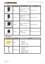
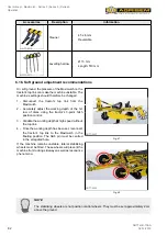
Page 81: ...ver entire width Ideal levelling and crumbling Sticky and wet soils NOTT 0312 Flexi Sem Shallow consolidation in wet conditions Good soil seed contact Sticky and wet soils NOTT 0313 OT O O T 0313 Flexi Pack Shallow consolidation in wet conditions Even consolidation Puddling heavy and wet soils 6 15 Accessories Accessories Description Information NOTT 0314 Scraper 80 x 10 mm Removable Weight 3 m 11...

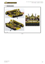
Page 82: ...ulch 2 Accurately adjust the working depth of the 1st row of discs using the tractor s 3 point hitch position control 3 Validate the working depth at high speed without the top link 4 Once the working depth has been set reconnect the tractor s top link to the Maximulch in the floating position The hitch pin must be centred in the elongated hole NOTT 0427 Fig 81 If the machine remains unstable late...

Page 83: ...ge of the field 6 18 Immobilising the tractor machine 6 18 1 Precautions In order to avoid moisture damage the machine should be parked if possible indoors or under cover When manoeuvring the machine pay attention to your surroundings Ensure that nobody is in the manoeuvring area Park with the machine on level solid ground if leaving parked for a long period of time it is advised the machine is le...

Page 84: ...k position 2 Fit chocks under the wheels 3 Open the in line hydraulic valve and operate the hydraulic take off 4 Turn off the tractor and remove the pin from the drawbar 5 Start up the tractor and move forward to clear the hitch 6 Retract the cylinder 7 Turn off the tractor and place all the hoses on the support bracket 8 Remove all the hoses and slowly move the tractor forward 9 After immobilisat...

Page 85: ...nd accessories that are in compliance with and have been checked in accordance with the applicable regulations Use standard secure wedging systems to avoid any risk of accident linked to unstable blocking Protect the hydraulic cylinder piston rods against corrosion Carry out lubrication in accordance with the maintenance plan in the user manual IMPORTANT The machine should as far as possible be st...

Page 86: ... have sharp edges Wear suitable personal protective equipment safety gloves goggles safety shoes when handling the components The machines are equipped with attachment points for lifting operations Pictograms enable them to be more quickly identified Handling must be carried out using appropriate lifting and wedging equipment and accessories for the load to be moved that are compliant and have bee...

Page 87: ...User manual Maximulch Series 3 Series 5 Series 6 Winter Storage Handling Transport 87 NOTT GB 708 A 06 12 2019 7 2 1 Maximulch series 3 NOTT 0400 Fig 85 ...

Page 88: ...User manual Maximulch Series 3 Series 5 Series 6 Winter Storage Handling Transport 88 NOTT GB 708 A 06 12 2019 7 2 2 Maximulch series 3 trailed NOTT 0433 Fig 86 ...

Page 89: ...User manual Maximulch Series 3 Series 5 Series 6 Winter Storage Handling Transport 89 NOTT GB 708 A 06 12 2019 7 2 3 Maximulch series 5 NOTT 0401 Fig 87 ...

Page 90: ...User manual Maximulch Series 3 Series 5 Series 6 Winter Storage Handling Transport 90 NOTT GB 708 A 06 12 2019 7 2 4 Maximulch series 6 NOTT 0402 Fig 88 ...

Page 91: ...hich might be thrown against the machine during transport The machines are equipped with attachment points for lifting operations Pictograms enable them to be more quickly identified Handling must be carried out using appropriate lifting and wedging equipment and accessories for the load to be moved that are compliant and have been checked in accordance with the applicable regulations To know the ...

Page 92: ...User manual Maximulch Series 3 Series 5 Series 6 Winter Storage Handling Transport 92 NOTT GB 708 A 06 12 2019 7 3 1 Maximulch series 3 mounted NOTT 0430 Fig 90 ...

Page 93: ...User manual Maximulch Series 3 Series 5 Series 6 Winter Storage Handling Transport 93 NOTT GB 708 A 06 12 2019 7 3 2 Maximulch series 3 trailed NOTT 0432 Fig 91 ...

Page 94: ...User manual Maximulch Series 3 Series 5 Series 6 Winter Storage Handling Transport 94 NOTT GB 708 A 06 12 2019 7 3 3 Maximulch series 5 NOTT 0431 Fig 92 ...

Page 95: ...User manual Maximulch Series 3 Series 5 Series 6 Winter Storage Handling Transport 95 NOTT GB 708 A 06 12 2019 7 3 4 Maximulch series 6 NOTT 0405 Fig 93 ...

Page 96: ...nts and bearings must not be cleaned with a high pressure washer or directly hosed down The housings screwed connectors and bearings are not watertight to VERY high pressure cleaning 8 1 2 Personal protective equipment PPE CAUTION The maintenance operations involve the handling of loads and materials requiring the wearing of personal protective equipment This personal protective equipment must be ...

Page 97: ...e equipment for welding work 8 1 6 Protection devices WARNING Go around the machine looking for any external damage and checking the condition of the protection devices The protection devices must be clean legible and in good condition If this is not the case contact the AGRISEM INTERNATIONAL customer service department in order to replace them 8 1 7 Tyres DANGER The tyres contain pressurised air ...

Page 98: ...dations does not represent any risk to health However avoid prolonged contact with the skin or avoid inhaling the vapours WARNING Protect against direct contact with oils by wearing gloves or protective cream Avoid the skin coming into contact with clothes that are soaked in oil Change clothes and rags when they are dirty Carefully wash all traces of oil off your skin with soap and hot water Do no...

Page 99: ...shoes impregnated with oil as hazardous waste The product or its packaging is technically recyclable not that it is or will be recycled The products will only be recycled under two conditions The sorting and recycling channel exists in your region The products have been correctly sorted Waste polluted by oil and used oil must be disposed of in line with current regulations Ensure that you do not c...

Page 100: ...hich this maintenance and servicing is carried out to suit the conditions Maintenance operations to be carried out prior to each use Check the hydraulic lines Check the lighting and signalling system Check the tyre pressure Maintenance operations to be carried out prior to folding Clean the folding areas Maintenance operations to be carried out after the first 10 hours of operation Check the tight...

Page 101: ...ns which do not correspond to the natural shape of the hose or pipe whether or not they are under pressure or bent e g separation of the layers bulges crushed areas bending Areas that are leaking Damaging or distortion of the end fitting affecting its leak tightness Slight superficial damage does not warrant replacement Hose becoming detached from the end fitting Corroded end fitting leading to re...

Page 102: ...e of movement is no less than the smallest authorised bending radius and or that the hose is not subject to tension Attach hydraulic hoses at the locations provided for this purpose Avoid mountings that may hinder the natural movement of the hose and modifications to its length WARNING Hydraulic hoses must not be painted Marking of hydraulic hoses Hoses must be replaced after 6 years from their da...

Page 103: ...B 708 A 06 12 2019 8 4 3 Clean the folding areas The folding areas must be cleaned each time before folding The accumulation of earth of stones or other obstacles may result in damage to the machine Failure to observe this requirement will void the warranty Series 3 NOTT 0408 Fig 95 ...

Page 104: ...User manual Maximulch Series 3 Series 5 Series 6 Servicing Maintenance 104 NOTT GB 708 A 06 12 2019 NOTT 0406 Fig 96 ...

Page 105: ...User manual Maximulch Series 3 Series 5 Series 6 Servicing Maintenance 105 NOTT GB 708 A 06 12 2019 Series 5 NOTT 0409 Fig 97 ...

Page 106: ...User manual Maximulch Series 3 Series 5 Series 6 Servicing Maintenance 106 NOTT GB 708 A 06 12 2019 Series 6 NOTT 0410 Fig 98 ...

Page 107: ...User manual Maximulch Series 3 Series 5 Series 6 Servicing Maintenance 107 NOTT GB 708 A 06 12 2019 8 4 4 Check the tightness of the nuts and screws Refer to the table NOTT 0229 Fig 99 ...

Page 108: ...f the start up section Carry out all the maintenance operations to be performed prior to each use 8 4 8 Clean the soil off the machine Clean the soil on the machine with a high pressure cleaner CAUTION If using a high pressure washer or steam cleaner it is essential to comply with the following points Do not clean the electrical and hydraulic components Never direct the high pressure washer or ste...

Page 109: ...ns The lubrication points are identified by this pictogram The machine must be lubricated regularly and after each pressure wash NOTT 0231 Fig 101 CAUTION The machine must be lubricated regularly and after each pressure wash This keeps the machine in good working order and reduces the costs of repairs and downtime Series 3 NOTT 0408 Fig 102 ...

Page 110: ...User manual Maximulch Series 3 Series 5 Series 6 Servicing Maintenance 110 NOTT GB 708 A 06 12 2019 NOTT 0406 Fig 103 ...

Page 111: ...User manual Maximulch Series 3 Series 5 Series 6 Servicing Maintenance 111 NOTT GB 708 A 06 12 2019 Series 5 NOTT 0409 Fig 104 ...

Page 112: ...User manual Maximulch Series 3 Series 5 Series 6 Servicing Maintenance 112 NOTT GB 708 A 06 12 2019 Series 6 NOTT 0410 Fig 105 ...

Page 113: ...f the hydraulic system are sealed see 8 4 5 Check the hydraulic system tightness and sealing page 108 NOTT 0407 Fig 106 8 4 11 Wear rings Wear rings must be replaced when the wearing strip is completely worn when wear causes jamming or hard spots The wearing strip is approximately 1 5 mm thick NOTT 0357 1 Fig 107 Depending on the mounting and options wear rings are provided at the pivot points of ...

Page 114: ...A 06 12 2019 NOTT 0411 Fig 108 8 4 12 Disc wear Discs must be replaced as soon as their diameters reach the values given below Disc New disc diameter mm Max acceptable wear diameter mm NOTT 0319 ø 460 ø 400 ø 510 ø 440 ø 560 ø 480 ø 610 ø 520 NOTT 0318 ø 510 ø 430 ø 560 ø 430 ø 610 ø 430 ...

Page 115: ...nnection with a warranty claim IMPORTANT Do not spray the high pressure water jet onto the hubs at the risk of breaking the seal and allowing water to enter In such a case no warranty claim will be considered 8 4 13 Tyre pressures System Mean pressure Maximum pressure Main axle 2 5 bar 4 1 bar 8 4 14 Wear part with carbide plates Wear parts with carbide plates are designed for working in fields wi...

Page 116: ...ntact and until the wheel no longer rotates 4 Turn the adjusting nut 1 anti clockwise stop when the wheel rotates freely 5 Check the brake by applying the handbrake a few notches and check that the wheels no longer turn 6 Release the handbrake 7 Check that the braking cylinder stroke is identical when the axle is in the working position and in the transport position If the cylinder stroke is ident...

Page 117: ... is the same on both rows of discs The Maximulch is not working at the same depth on the right and the left Tractor lift links The tractor s lift links must be set to the same length A ridge forms between 2 passes of the Maximulch Border spreading disc Adjust the border spreading disc setting Clogging of the discs Working depth Reduce the working depth of the Maximulch Disc wear Replace the discs ...

Page 118: ...raulically assisted Hitch category Cat 3 Transport wheels 500 45x22 5 10 1 1 Fixed tractor mounted 3 m 3 50 m 4 m Working width m 3 3 5 4 Transport width without accessories m 3 3 5 4 Min max recommended power Hp 160 210 200 250 240 290 Weight with bolt safety system and Ø526 cage roller kg 2152 2435 2738 Weight with spring safety system and Ø526 cage roller kg 2542 2903 3284 Number of discs 21 25...

Page 119: ...ce 89 cm Working depth 30 cm Frame cross section 100 x 100 discs 120 x 120 blade Disc pressure 100 200kg Braking Hydraulically assisted Hitch category Cat 3 Transport wheels 500 45x22 5 10 2 1 Fixed trailed 3 m 4 m Working width m 3 00 4 00 Transport width without accessories m 3 00 4 00 Min max recommended power Hp 180 320 240 450 Weight with spring safety system and Ø526 cage roller kg 5220 6220...

Page 120: ...andard Height under frame 57 cm Inter disc clearance 89 cm Working depth 30 cm Frame cross section 100 x 100 discs 120 x 120 blade Disc pressure 100 200kg Braking Hydraulically assisted Hitch category Cat 3 Transport wheels 500 45x22 5 4 m 5 m 6 m Working width m 4 00 5 00 6 00 Transport width without accessories m 3 00 3 00 3 00 Min max recommended power Hp 200 300 280 380 350 450 Weight with spr...

Page 121: ...PE personal protective equipment ha hectare unit of area ISOBUS standard data transfer system kg h kilogram per hour unit of mass flow kg ha kilogram per hectare unit of density km h kilometre per hour unit of speed l litre unit of volume l min litre per minute unit of flow LS load sensing hydraulic load detection system m metre unit of length mm millimetre unit of length rpm revolution per minute...

Page 122: ...User manual Maximulch Series 3 Series 5 Series 6 122 NOTT GB 708 A 06 12 2019 ...

Page 123: ...ATION OF CONFORMITY WITH THE MACHINERY DIRECTIVE The manufacturer referred to above certifies that the new equipment described below MAXIMULCH Complies with the provisions of the amended Machinery directive Directive 2006 42 EC and with the applicable national legislation Ligné 21 May 2013 Michal GUZOWSKI CEO ...

Page 124: ...User manual Maximulch Series 3 Series 5 Series 6 Appendices 124 NOTT GB 708 A 06 12 2019 ...

Page 125: ...F CONFORMITY WITH THE MACHINERY DIRECTIVE The manufacturer referred to above certifies that the new equipment described below MAXIMULCH Complies with the provisions of the amended Machinery directive Directive 2006 42 EC and with the applicable national legislation Ligné 21 May 2013 Michal GUZOWSKI CEO ...

Page 126: ......

Page 127: ... user Make model and et power of tractor used Type of soil clay Utilised agricultural land belonging to the farm Place date Purchaser s signature and stamp Dealer s signature and stamp We acknowledge that we have read the whole of the user manual and the warranty terms to which we adhere AGRISEM INTERNATIONAL SA 535 rue Pierre Levasseur CS 60263 44158 ANCENIS FRANCE Tel 33 0 2 51 14 14 40 Fax 33 0...

Page 128: ......

Page 129: ... type Make of tractor used Model of tractor used Power rating Detailed description and alleged cause of the incident Date of breakdown Current date Part reference Quantity Description Send parts requested YES Credit note requested YES Photographs attached YES Parts returned Freight costs payable by the sender YES Result of inspection by AGRISEM INTERNATIONAL Comments Date Signature Technical manag...

Page 130: ......
Reviews: