background image

sales@agrotkindustrial.com

https://www.agrotkindustrial.com/

P14

OPERATION INSTRUCTIONS

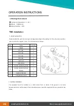
main shaft—(direction of the rim installation surface is inside)

—main shaft — tower spring (big side inside )
—wheel —quick nut suitable cone (small side inside) —quick nut

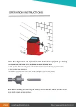
Note: When install or remove the wheel,it is not allowed to slide the wheel on main shaft
screw,to avoid any scratching.

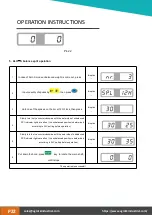
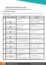
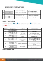
1)turn on the power switch
2)input a b d value

(Automatic input gauge is optional function .No automatic gauge please

enter manually)

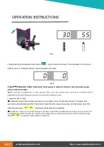
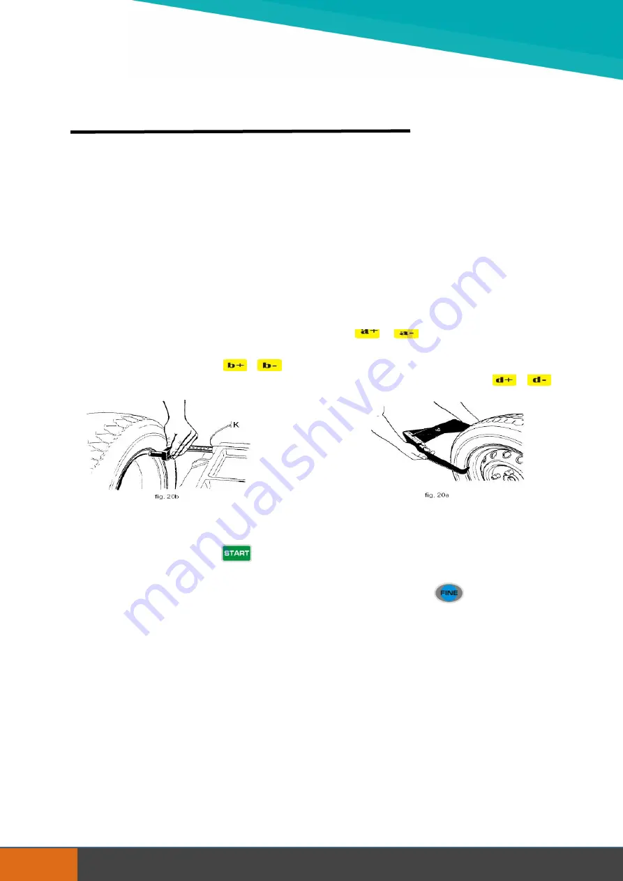
distance (a) value: pull the scale to the position as in pic.1 and hold it for 4 seconds, read this value

from measuring scale, and input the value manually through

.

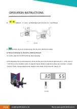
width (b) value: read it directly from the rim or measure it by equipped caliper as in pic.2, and

input the value manually through

diameter (d) value: read it directly from the rim, and input the value manually through

Pic.1

Pic.2

4) put down the hood or press

key to rotate the wheel

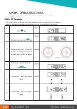
5) After the wheel stops, the digital tube displays unbalanced weight

press

key to read actual

unbalance weight.

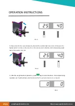
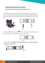
6) Slowly rotate the tire counterclockwise by hand until the indicator light outer is all on. At this
time, the highest point (12 o' clock) of the outer rim is the correct point of the unbalance. Add
corresponding weight lead at this position.

See Pic.3

Summary of Contents for AGT-WB24

Page 1: ...PRODUCT MANUAL AGT INDUSTRIAL Wheel Balancer Ver 1 1 3 https www agrotkindustrial com Model AGT WB24...

Page 2: ...sales agrotkindustrial com https www agrotkindustrial com P2 TABLE OF CONTENTS 2 31 TO THE OWNERS 3 31 TABLE OF CONTENTS SAFETY PRECAUTIONS 4 31 OPERATION INSTRUCTIONS 7 31 NOTES 31 31...

Page 3: ...cautions and maintenance procedures as described in this manual BEFORE OPERATION Thoroughly read and understand the instructions given in this manual before operation Refer to the Safety Label section...

Page 4: ...c installations and couplings connect firmly and all the safe signs stick on the suitable positions clearly 1 Operator should be familiar with all functions of the unit 2 Make sure all guards and shie...

Page 5: ...with moving parts Prolonged exposure to loud noise can cause hearing impairment or hearing loss Wear suitable hearing protection such as earmuffs or earplugs Operating equipment safely requires the o...

Page 6: ...or cardboard NOT BODY PARTS to check for suspected leaks Wear protective gloves and safety glasses or goggles when working with hydraulic systems DO NOT DELAY If an accident occurs see a doctor famil...

Page 7: ...than 0 6m should be left between the back of the balancing machine and the wall to ensure good ventilation and heat dissipation Note leave enough space on the left and right side of the balancing mac...

Page 8: ...l kinds of car wheel shape Max Wheel Weight 65KG Motor Power 250W Voltage 110V 60HZ 220V 50HZ Balance Precision 1g Balance Speed about 200r min 1 standard mode 6 aluminum alloy balance mode Balance Cy...

Page 9: ...mperature 5 50 Altitude 4000 meter Relative Humidity 85 TWO Installation installationinstallationinstallat 1 unpacking inspection Check whether the parts are missing or damaged according to the packin...

Page 10: ...he position of the mounting hole of the machine base should be fixed by expansion screw 4 Main shaft screw installation Install the equipped screw on the main shaft and tighten it see below picture No...

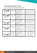
Page 11: ...s The unbalance block is clipped on the alignment planes at the two edges of the rim ALU1 balance mode 1 Turn on the machine 2 Input a b d value 3 Press the ALU key to turn on the mode light 4 Start w...

Page 12: ...d value 3 Press the ALU key to turn on the mode light 4 Start wait until it stops paste the unbalanced block on the alignment plane inner and clip the unbalanced block at outer ALUS balance mode 1 Tur...

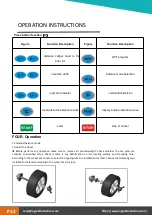
Page 13: ...start stop or cancel OPERATION INSTRUCTIONS sales agrotkindustrial com https www agrotkindustrial com P13 FOUR Operation 1 Standard balance mode 1 install the wheel Before perform any operation make...

Page 14: ...as in pic 1 and hold it for 4 seconds read this value from measuring scale and input the value manually through width b value read it directly from the rim or measure it by equipped caliper as in pic...

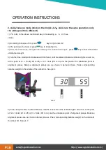
Page 15: ...light inner is all on At this point the highest point 12 o clock on the inner rim is the correct point of unbalance Add corresponding weight lead at this position See pic 4 Pic 4 8 After the weight le...

Page 16: ...5 turn the tires slowly Anti clockwise with the hand until the lateral imbalance indicator lights are all on at the point at 12 o clock 12H is off or 9 o clock 9H is on are the position for unbalance...

Page 17: ...1 and alu 2 methods cann t guarantee sufficient balance accuracy Choose this balance mode 1 Input aI aE d value aI distance value Pull out the ruler head as it is shown in pic 9 first and hold it at...

Page 18: ...tate 3 There are two ways to check the unbalanced result 3 1 set the option SLC to OFF stick the block manually 3 2 Rotate slowly the tire anticlockwise by hand until the outer side of indicator light...

Page 19: ...t plane Balance alignment planes are as shown in below pictures Paste corresponding balance weight on the inside of the wheel rim See pic 11 Pic 11 3 4 After placing the balanced lead press key to rot...

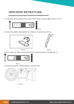
Page 20: ...until the outside of indicator lights are all on Pic 14 Pic 14 4 2 Tear out the suitable weight lead Pic 15 and place it on head of ruler Pic 16 Pic 15 Pic 16 4 3 Pull out the ruler until to see the...

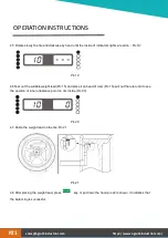
Page 21: ...of ruler Pic 16 pull out the ruler until to see the position of inner unbalance point on rim inside Pic 20 Pic 20 4 7 Paste the weight lead on the tire Pic 21 Pic 21 4 8 After placing the weight lead...

Page 22: ...SP1 indicator lights are all on the unbalanced position is determined according to SLC setting before operation display 5 Slowly turn the tire counterclockwise until the outer side of unbalanced SP2...

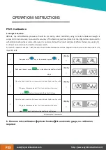
Page 23: ...f rim input rim data 6 Distance ruler calibration optional function No automatic gauge no calibration required 1 Press and hold key at the meanwhile press key display 2 Put down the hood press key to...

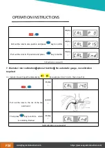
Page 24: ...on optional function No automatic gauge no calibration required 7 1 Install a tire and input the diameter by for example if it is 14 inch then in put 14 display Pull out the ruler to the rim of the ti...

Page 25: ...ething wrong 2 Computer panel is something wrong 1 Check or replace position sensor 2 Check or replace computer panel 5 1 Travel switch is something wrong 2 Computer panel is something wrong 1 Check o...

Page 26: ...w varies 327 335 when rotate the ruler rod to the other direction 5 Width ruler sensor optional Value showed in window varies 327 335 when rotate the ruler rod to the other direction 6 Pressure sensor...

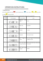
Page 27: ...ed Function definition option 1 Unbalanced weight hidden 5 10 15 2 Prompt tone open closed 3 brightness 1 8 grade 4 Inch switch Inch open inch closed 5 ALU to paste at 9 O clock ALU mode to paste at 1...

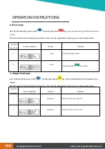
Page 28: ...od to start 2 hood Put down hood key to start 3 Weight Unit Setup In normal standy mode press at mean time press key it will automatically switch between two states The machine has the following funct...

Page 29: ...ss key display 2 Put down the hood press key display 3 Demount the tire from the rim and make a mark then mount it again in the opposite position at 180 degree operate 4 When done put down the hood pr...

Page 30: ...nd then mount it again to make these two points overlap with each other operate 8 When done put down the hood press key display Unbalanced weight is less than before is successful sales agrotkindustri...

Page 31: ...sales agrotkindustrial com https www agrotkindustrial com P31 NOTES...

Page 32: ......

Reviews:

Related manuals for AGT-WB24