background image


Ae-man-817-0.0 v2.3                                                                        56                                                                                      AGUILERA ELECTRONICA 

AE/SA-IDC  AE/SA-GAT COMMUNICATION  INTERFACE


MODBUS/TCP 

TCP Passive Connection 

OPTIMUS 

TCP Active Connection 

GATEWAY 

TCP Passive Connection 


6.2.3.3.1  TCP


P

ASSIVE 

C

ONNECTION

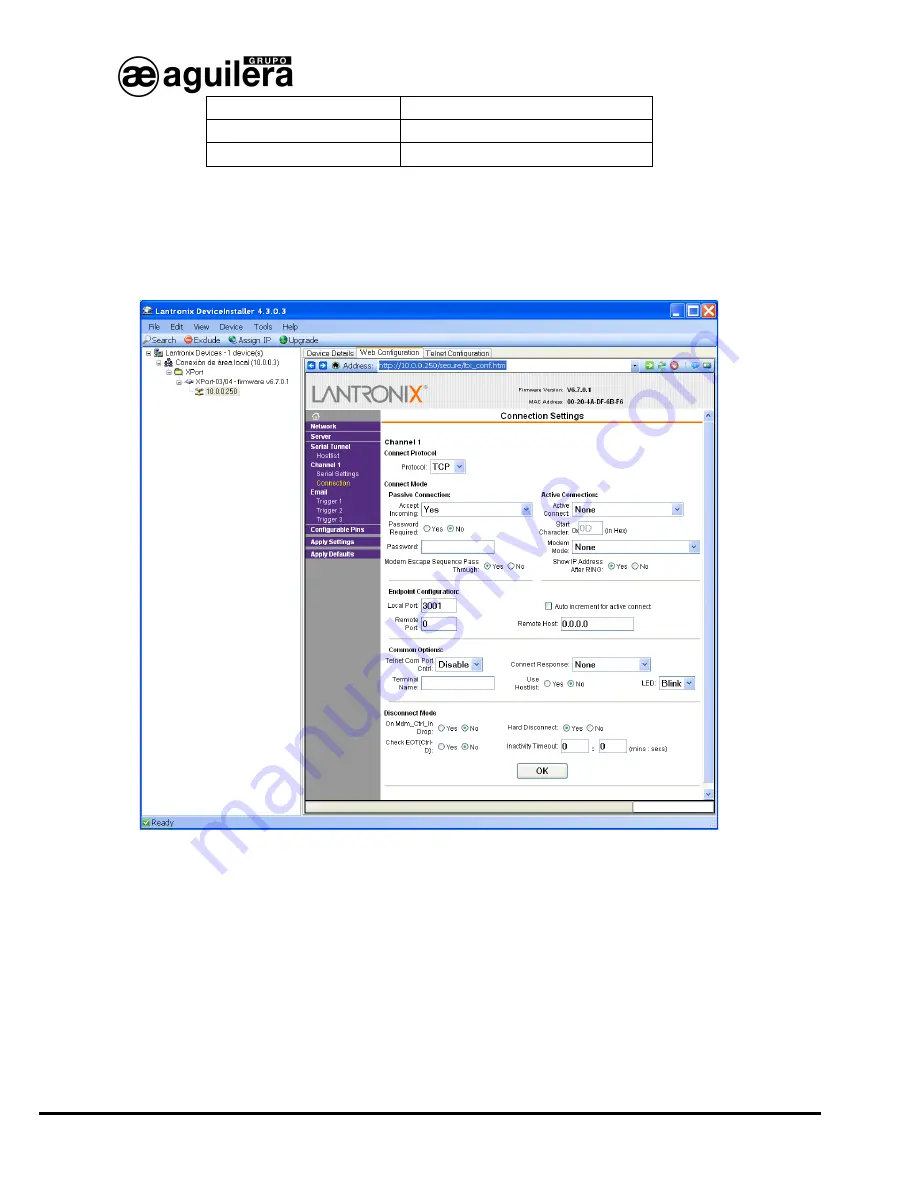
This operation mode should be programmed for the AE/SA-GAT  operation in MODBUS/TCP  and 
GATEWAY mode. This is the default programmed mode. 
 
The following screen will be shown when selecting the 

Channel 1 - Connection

 option on the left panel.   


The following values should be selected:  


Connect Protocol: 


o


Protocol TCP 


Connect Mode : 

o


Passive Connection : 

Accept Incomming 

YES 

o


Active Connection :  

Accept Incomming 

None 


Endpoint Configuration :


o


Local Port :  


3001 or the Port we want to use. 

o


Remote Port : 


Summary of Contents for AE/SA-GAT

Page 1: ...Algorithmic system Communication Interface AE SA IDC AE SA GAT Installation Manual VERSION 2 3 MAR 12...

Page 2: ......

Page 3: ...1 Aguilera 14 2 6 2 MODBUS RTU 15 2 6 3 MODBUS TCP 16 2 6 4 N2 PROTOCOL 17 2 6 5 ESPA 4 4 4 18 2 6 6 Optimus 19 2 6 7 Gateway 20 2 7 END OF THE PROCESS 21 3 PARAMETER CONFIGURATION OF MODBUS PROTOCOL...

Page 4: ...on of the serial port 42 6 1 2 3 Operation modes 44 6 1 2 3 1 TCP Server 44 6 1 2 3 2 TCP Client 46 6 1 2 4 Saving data and resetting 47 6 2 CONFIGURATION OF THE LANTRONIX XPORT MICRO SERVER 48 6 2 1...

Page 5: ...AE SA IDC AE SA GAT COM1 RS 232 RS 232 COM2 RS 485 RS 485 COM3 ARCNET RS 485 ETHERNET TCP IP The equipment configuration is made through an external software and the configuration values are kept in t...

Page 6: ...Ae man 817 0 0 v2 3 4 AGUILERA ELECTRONICA AE SA IDC AE SA GAT COMMUNICATION INTERFACE...

Page 7: ...uipped with the following connectors AE SA GAT is equipped with the following connectors 1 1 COM1 RS 232 It has a DB9 connector with the following pin assignment Pin 2 TXD Pin 3 RXD Pin 5 GND The conn...

Page 8: ...Pin 3 Common It has two status indicator LEDs LEDs Yellow reception Red transmission 1 2 1 END OF LINE RESISTORS Through the selectors placed at the bottom of the equipment an internal end of line res...

Page 9: ...n Yellow failure depending on the number of flashes Number of flashes Meaning 1 Wrong address 2 Error in hardware diagnostics 3 Duplicated network address 4 There are no more nodes in the network 1 3...

Page 10: ...connection Off Without activity Orange 10 Mbps Orange Half Duplex Green 100 Mbps Green Full Duplex 1 5 POWER SUPPLY The Communication Interface is fed through the connector by means of a 9V DC 0 5A ex...

Page 11: ...izer AGE42IDC 2 1 PORT SELECTION After running the application the following window is shown where we will select the communication port we are going to use for communication with the Communication In...

Page 12: ...process can be repeated by pressing the button Detect or back to the previous step and selecting another communication port if we have made a mistake NOTE Unless the interface has not been customized...

Page 13: ...step the programme shows the currently configured work mode in the equipment allowing us to leave it or select another of the modes available Operation modes available change depending on the type of...

Page 14: ...rovided with maintaining the same work mode but allowing some of the values to be modified Obtaining a previously created customization from a file that was saved for a later use or as a back up copy...

Page 15: ...evice allowing for failure signalization in the communications with third party equipments As a general rule enabling this option is recommendable as any failure in the communications between the Inte...

Page 16: ...should be configured at the same speed o 39 Kbps o 78 Kbps o 156 Kbps o 312 Kbps COM1 RS 232 Port This port will be used for connecting to a PC through the AGE43 Control Station software or AGE44 Remo...

Page 17: ...5 Port It is the default port for the interface to communicate with the master Modbus equipment The configuration of this port should be the same as the other devices of the Modbus network o Speed 240...

Page 18: ...same way and with the same parameters as the port of the central unit to be connected o COM1 RS 232 o COM2 RS 485 Speed 2400 4800 9600 19200 38400 57600 bauds Parity None Even Odd Stop Bits 1 bit 2 b...

Page 19: ...9600 19200 38400 57600 bauds o Parity None Even Odd o Stop Bits 1 bit 2 bits Port COM2 RS 485 This is the default port for the interface to communicate with the equipment with the N2 Protocol Configur...

Page 20: ...unicate with the equipment with ESPA 4 4 4 Protocol Configuration of this port should be the same as the device to be connected o Speed 2400 4800 9600 19200 38400 57600 bauds o Bits data 7 bits 8 bits...

Page 21: ...the port of the central unit to be connected o COM1 RS 232 o COM2 RS 485 Speed 2400 4800 9600 19200 38400 57600 bauds Parity None Even Odd Stop Bits 1 bit 2 bits Once parameter selection has finished...

Page 22: ...for the GAT to communicate with the central unit It should be configured in the same way and with the same parameters as the port of the central unit to be connected o COM1 RS 232 o COM2 RS 485 Speed...

Page 23: ...iting are produced an error message is shown on the screen The error message could also be produced if the Interface hardware 2 version is not compatible with the customization Please contact Aguilera...

Page 24: ...Ae man 817 0 0 v2 3 22 AGUILERA ELECTRONICA AE SA IDC AE SA GAT COMMUNICATION INTERFACE In both cases we exit the programme by pressing the Finish button...

Page 25: ...ied out by the system integrator If the option Use the classic customization for Modbus has been selected values used in version 1 0 of the Interface will be applied For further information please con...

Page 26: ...s to define the base address of the table of customization limits as well as registers we want to be available for the master Modbus equipment Any address can be customized but in order to allow the c...

Page 27: ...case of conflict of addresses produced by overlapping an error message will be shown 3 3 3 GENERAL ZONES It allows to define the base address of the sub table of general counters of zones as well as...

Page 28: ...ally updated To allow compatibility with installations with equipments with firmware series 1 absolute address 100 should be assigned 3 3 5 SECTOR STATUS It allows to define the base address of the su...

Page 29: ...of the sector status or an absolute address can be indicated In such case addresses for each register are automatically updated To allow compatibility with installations with equipments with firmware...

Page 30: ...e registers we want to be available for the master Modbus equipment The sub table address may be adjacent to the sub table of the system clock or an absolute address can be indicated In such case addr...

Page 31: ...resetting or an absolute address can be indicated In such case addresses for each register are automatically updated To allow compatibility with installations with equipments with firmware series 1 ab...

Page 32: ...ICATION INTERFACE 3 6 REPORTED STATUS It allows to define which status are sent for each register if they can be multiple or single and in this case the value to be taken Once parameters have been con...

Page 33: ...dification will only be necessary if needed to be adapted to the implementation carried out by the system integrator 4 1 GENERAL It allows to define general parameters of Pager Options and Call End 4...

Page 34: ...ers that will receive the message The Tone field shows the number of acoustic alerts which will be received on the pager 4 2 1 OUTPUTTING MESSAGES When pressing the Edition key the different fields to...

Page 35: ...they can be eliminated through the Eliminate button A counter with the total length of the message defined is shown at the lower part A Preview window is shown on the lower part whose dimensions can...

Page 36: ...ill receive them and the number of alert tones 4 different types of failure messages can be received which can be activated according to the needs and whose content may be edited The field Pager es sh...

Page 37: ...RAL PARAMETERS Parameters relating to the public address message which will be played in the Optimus equipment when producing any alarm in the algorithmic central unit are configured in this window Id...

Page 38: ...ral unit to a specific public address group Each zone can only be associated to one public address group The window allows to manage 1 024 zones which is the maximum number of zones that can exist in...

Page 39: ...A IDC AE SA GAT COMMUNICATION INTERFACE The window allows to select many zones and assign them to the currently selected group in one single operation Press the Next button once zones have been assign...

Page 40: ...Ae man 817 0 0 v2 3 38 AGUILERA ELECTRONICA AE SA IDC AE SA GAT COMMUNICATION INTERFACE...

Page 41: ...s by means of a WEB browser In order to do that we will open our browser and enter the micro server IP Address The IP Address assigned to the AE SA GAT equipment is 10 0 0 250 by default If this Addre...

Page 42: ...ssing the latest application version from the Moxa web is also possible Download link http www Moxa com support download aspx d_id 1358 For the correct operation of the application the PC firewall fro...

Page 43: ...ser installed in the PC It is also possible to search all devices connected to the Ethernet network where we are connected to This is very useful in installations where there are two or more equipment...

Page 44: ...as the network mask The rest of parameters are not usually necessary but it is appropriate to confirm it with the network administrator where the Communication Interface is going to be installed Afte...

Page 45: ...is no relationship with the serial Port configuration of the Interface that as we have seen above it is carried out through the AGE42IDC Customizer and it is not related at all with the configuration...

Page 46: ...mode MODBUS TCP TCP Server OPTIMUS TCP Client GATEWAY TCP Server 6 1 2 3 1 TCP SERVER This operation mode should be programmed for the operation of AE SA GAT in MODBUS TCP mode and GATEWAY This is th...

Page 47: ...IDC AE SA GAT COMMUNICATION INTERFACE Next press Advanced settings to modify some parameters ensuring that they correspond with the ones of the image If any data has been modified press Submit and the...

Page 48: ...by pressing Advanced settings These are the parameters to be modified Mode Select TCP Role Select TCP Client Connection Control Select Start up for the equipment to be automatically connected with th...

Page 49: ...cro sever configuration has finished configuration data should be saved and the equipment restarted Select Save and Restart on the left panel for changes to take effect The following message will be s...

Page 50: ...to the AE SA GAT equipment It is included in the CD accompanying the AE SA GAT which can be found in the Utilities Lantronix directory It is also possible to access the last version of the application...

Page 51: ...the PC Ethernet Port to the AE SA GAT equipment through a cable with RJ45 connectors The green LED of the XPort micro server should be illuminated Execute Device Installer The following screen should...

Page 52: ...nected to This is very useful in installations where there are two or more equipments connected 6 2 2 ASSIGNMENT OF AN IP ADDRESS Having selected the device we want the IP Address to be modified press...

Page 53: ...e installed for ensuring the correct operation and prevent from address conflict with other equipments Press Next to continue Press the Assign button for saving data in the AE SA GAT communication int...

Page 54: ...Reply make sure that the AE SA GAT communication interface is connected to the network and the IP Address assigned is valid for the network segment where working If you are not sure check it with you...

Page 55: ...AE SA GAT COMMUNICATION INTERFACE When pressing Accept the following screen will be shown 6 2 3 1 NETWORK CONFIGURATION NETWORK By selecting the Network option on the left panel we will access the pag...

Page 56: ...Communication Interface is going to be installed Press the OK button after entering the required data The text Done will be shown for a few seconds Press Apply Settings when finishing for modificatio...

Page 57: ...elated at all with the configuration of the serial Port of the algorithmic central unit the Interface will be connected to Modification of these data will make the AE SA GAT equipment not to work corr...

Page 58: ...mmed for the AE SA GAT operation in MODBUS TCP and GATEWAY mode This is the default programmed mode The following screen will be shown when selecting the Channel 1 Connection option on the left panel...

Page 59: ...OMMUNICATION INTERFACE o Remote Host 0 0 0 0 The rest of parameters as shown on the screen If data has been needed to be modified press the OK button The text Done will be shown for a few seconds Pres...

Page 60: ...Connect Protocol o Protocol TCP Connect Mode o Passive Connection Accept Incomming NO o Active Connection Accept Incomming Auto Start Endpoint Configuration o Local Port 3001 or the Port we want to u...

Page 61: ...onfiguration has finished it is necessary to save the configuration data and restart the equipment Select Apply Settings on the left panel for modifications to take effect The following message will b...

Page 62: ...Ae man 817 0 0 v2 3 60 AGUILERA ELECTRONICA AE SA IDC AE SA GAT COMMUNICATION INTERFACE...

Page 63: ...IAL PORTS Interface AE2NET AE SA IDC Interface AE2NET AE SA IDC C C GND COM 2 RS 485 12 Vcc 9 Vcc COM 1 RS 232 On Rx COM 3 ARCNET COM 1 RS 232 COM 2 RS 485 Tx Rx Tx Rx Tx C C GND COM 3 RS 485 AE2NET R...

Page 64: ...E SA IDC EN EL COM1 O EN EL COM2 DE LA CENTRAL DEPENDIENDO DE LA PERSONALIZACION DE LA MISMA COM1 RS 232 EQUIPO DE CONTROL MOD BUS O N2 METASYS EQUIPO DE CONTROL MOD BUS O N2 METASYS Interface AE2NET...

Page 65: ...OR COM 2 OF THE CENTRAL UNIT ACCORDING TO ITS CUSTOMIZATION CONECTAR EL CABLE DEL INTERFACE AE SA IDC EN EL 485 1 O EN EL 485 2 DE LA CENTRAL DEPENDIENDO DE LA PERSONALIZACI N DE LA MISMA CONNECT THE...

Page 66: ...08 04 Fax 93 381 07 58 EAST OFFICE Tel 628 92 70 56 Fax 91 754 50 98 NORTHWEST OFFICE C Jos Luis Bugallal Marchesi 9 15008 A Coru a Tel 98 114 02 42 Fax 98 114 24 62 SOUTH OFFICE Edificio METROPOL 3...

Reviews: