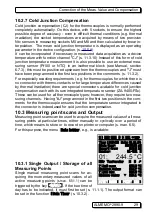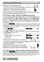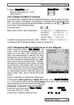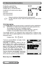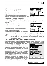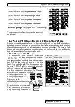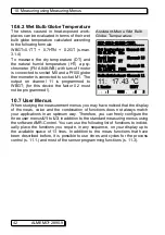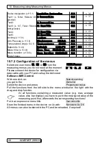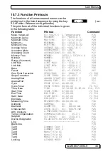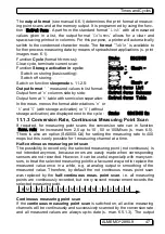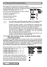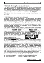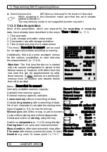
10. Measuring using Measuring-Menus
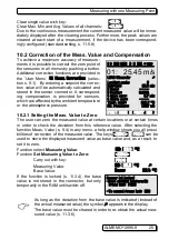
help menu for
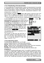
Averaging
.
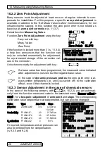
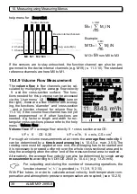
Example:
M13=
M
from M0 to M3
If the sensors are to stay untouched, the function channel can also be pro-
grammed to the device internal channels (e.g. M19) (s. 11.3.10). The standard
reference channels are here M0 to M1.
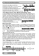
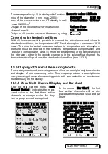
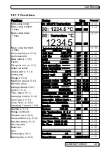
10.4.9 Volume Flow Measurement
The
volume flow
in flow channels can be cal-
culated by multiplying the average flow velocity
v
and the cross-section surface. The func-
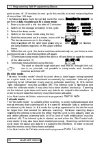
tions needed for this purpose can be accessed
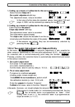
via the ´User menu´ U3
Volume flow
(see on
the right); these are a flow channel with averag-
ing, the functions ´diameter´ and ´cross-section
´, and a function channel for volume flow (s.
11.3.10) If the volume flow channel has not yet
been programmed or if other functions are
needed, e.g. factor or length and width for rec-
tangular cross-sections, please refer to the help
menu
Volume flow
.
Volume flow
VF = average flow velocity
v
• cross section area CS:
VF =
v
. CS
. 0.36
VF = m
3
/h,
v
= m/s, CS = cm
2
For rough air volume measurements at air vents the
average flow velocity
v
can be determined by a
time-based averaging
(s. 10.4.5 a. man. 3.5.5).The
rotating vane must be applied at one end, the averaging has to be started and
it is necessary to proceed uniformly over the whole cross-sectional area and to
stop the averaging when the other end of the cross-sectional area is reached.
Alternatively, the average flow velocity can also be determined by single
array
measurements
according to VDI/VDE 2640 (s. 10.4.4 ) (e.g. 13.24 m/s).
For outputting and storing the number of measuring operations, the
function channel ´
n(t)
´ is provided (s. 11.3.9, 11.3.10).
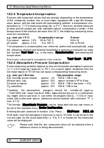
With Pitot tubes, in order to calculate actual velocity, both temperature com-
pensation and atmospheric pressure compensation are required; (see 10.2.5)
38 ALMEMO
®
2890-9
M13
=
∑
i
=
M0
n
=
M3
M
i
/
N
M
=
∑
i
=
Bk2
n
=
Bk1
M
i
/
N
M0 M1 M2 M3
M4
00
10
20
30
03
13
23
33
04
14
24
34
01
11
21
31
02
12
22
32
1. Channel
2. Channel
3. Channel
4. Channel
05
15
25
35
Device internal channels
Difference M01-M00
Sensor channels
Avg. value M(n)
C © REC COM l© ©l R01 * ´´´´´´µµµµ
±±±±±±±±±±±±±±±±±±±±±±±±±±±±±±±±±±±±
01: 11.67 mls Volocity
|¹¹¹¹¹¹¹¹¹¸¹¹¹¹¹¹¹¹¹¸¹¹¹¹¹¹¹¹¹¸¹¹¹¹¹¹¹¹¹¸¹¹¹¹¹¹¹¹¹|¹¹¹¹¹¹¹¹¹¸¹¹¹¹¹¹®®®¸®®®®®®®®®¸®®®®®®®®®¸®®®®®®®®®|
5.00 S220 mls 15.00
Damping:
20
Averaging mode:
CONT
Average value:
13.24 mls
Counts:
12
Volume flow:
11: 8343. m
3
/h
Diameter:
150 mm
Cross section:
175 c¥
START MANU M PRINT ESC


