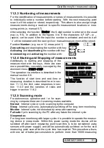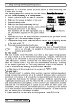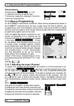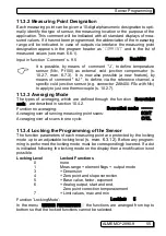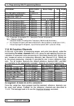
11. Programming With Programming-Menus
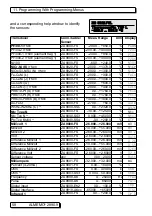
Transducer
Conn./Cable/
Sensor
Meas. Range
Dim Display
Wet bulb globe temperature
ZA 9000-FS
°C
WBGT
Cold junction temperature
any
°C
CJ
Volume m
3
/
h Mb1 · Q
any
m
3
/
h
Flow
Timer
beliebig
0...65000
s
Time
Temp. for Refrigerant R22 °
FDA602Lx
-90.0...+79.0
°C
R22
Temp. for Refrigerant R23 °
FDA602Lx
-100.0...+26.0
°C
R23
Temp. for Refrigerant R134a °
FDA602Lx
-75.0...+101.0
°C
R134
Temp. for Refrigerant R404a °
FDA602Lx
-60.0...+65.0
°C
R404
Temp. for Refrigerant R407c °
FDA602Lx
-50.0...+86.0
°C
R407
Temp. for Refrigerant R410 °
FDA602Lx
-70.0...+70.0
°C
R410
Temp. for Refrigerant R417a °
FDA602Lx
-50.0...+70.0
°C
R417
Temp. for Refrigerant R507 °
FDA602Lx
-70.0...+70.0
°C
R507
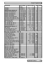
TC = Temperature Compensation, PC = Atmospheric Pressure Compensation,
Mbx = Reference channels
* Calculated variables of humidity (Mb1=Temperature, Mb2=Humidity/Humid temp.)
++ only via special connectors with internal characteristic, others available by request) (see 10.3.11)
°
8 measuring ranges for refrigerants - only with device option R (Mb1 = pressure in mbar)
11.3.10 Function Channels
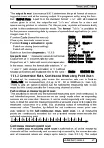
At the end of the table of measuring ranges and units (see above) under the
sub-heading
Function channels
there is a group for representing function pa-
rameters in measured value processing or calculated results from linking cer-
tain measured values on measuring channels (see Manual 6.3.4). Reference
to the actual measuring channels is provided by one or two reference chan-
nels. For all function channels the default reference channels Mb1 and Mb2
are available on the appropriate connector; these do not need programming.
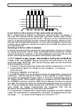
Function
Function channel
Ref. Channel 1
Ref. Channel 2
* Humidity variables cap.
to 3. or 4.Channel
Mb1=Temperatur Mb2=Humidity
* Humidity variables psy.
to 3. or 4.Channel
Mb1=TT
Mb2=HT
Function parameters (Mb1) to 2., 3. or 4.Channel
Mb1= 1.Channel
Difference (Mb1-Mb2)
to 2., 3., 4.Chan. (Mb1) Mb1= 1.Channel Mb2=M00
Avg. value over Mb2..Mb1 to 2., 3., 4.Chan. (Mb1) Mb1= 1.Channel Mb2=M00
Sum over Mb2..Mb1
to 2., 3., 4.Chan. (Mb1) Mb1= 1.Channel Mb2=M00
q
/
M01
−
M00
to 2., 3., 4.Chan. (q)
Mb1= 1.Channel Mb2=M05
WBGT
to 2.Channel (GT)
Mb1= 1.Channel Mb2=M00
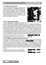
Arrangement of channels on the connectors :
Once the range has been programmed the standard reference channels can
be used (see above). Settings for the reference channels are described in
11.4.6. The best approach is to use the
Function channell
assistant.
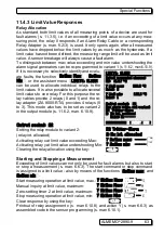
60 ALMEMO
®
2890-9


