F08D/F10D
F08D/F10D
6-2
6-2
Démontage
(1) Déposer le godet en position
stable sur le sol.
(2) Actionner la vanne de bloca-
ge à boisseau sphérique (1-2) de la
manette pour l´hydraulique acces-
soire (4-9/5) (position horizontale)
et verrouiller le godet.
(3) Incliner le système d´échange
rapide et sortir en marche arrière.
TRES IMPORTANT
La plaque de fabrication se trouve sur
le dos du godet, à droite en-dessous du
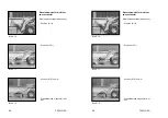
support transversal (6-2/flèche).
6.1.2 Palettiseur
TRES IMPORTANT
Le montage/démontage se fait de
manière analogue que pour le godet
(chapitre 6.1.1).
DANGER
- Des deux côtés, les deux boulons
du système d´échange rapide
doivent se trouver dans les trous
de forage prévus de la suspension
de palettiseur et être distinctement
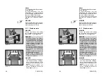
repérables de vue latérale (6-4/2).
- Répartir la charge de manière
égale sur les deux fourchons et
empêcher son déplacement ou
sa chute.
- Mettre la charge contre le dos de la
fourche et redresser le palettiseur.
- Disposer les deux fourches à
distance égale du centre (6-5/
flèche) et les bloquer.
TRES IMPORTANT
- Les fourches sont correctement
bloquées, lorsque les deux
leviers de blocage repliables sont
posés dans toute la longueur sur
le support de la fourche.
- La plaque de fabrication se trouve
sur le dos du support supérieur
de la fourche (6-4/1).
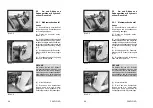
Dismounting
(1) Place the bucket firmly on the
ground.
(2) Actuate the ball block valve
(1-2) of the hand lever for the auxi-
liary hydraulics (4-9/5) (vertical
position) and unlock the shovel.
(3) Tilt the quick-change device
and reverse out.
NOTE
The type label is on the rear of the
bucket, on the right below the cross
arm (6-2/arrow).
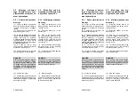
6.1.2 Fork-lift attachment
NOTE
Mounting and dismounting are
carried out in the same way as for
the standard/lightweight bucket
(chapter 6.1.1).
DANGER
- Both bolts of the quick-change
device must be in the bore holes
of the fork-lift attachment and
must be clearly visible (6-4/2).
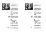
- Distribute the load equally on both
fork tines and secure it against
moving and falling off.
- Rest the load at the rear of the fork
and tilt the fork lift attachment.
- Position both fork tines at an equal
distance from the center (6-5/
arrows) and lock them.
NOTE
- The fork tines are locked correct-
ly when the two tiltable locking
levers are fully positioned on the
fork carrier.
- The type plate is on the rear of
the fork-lift attachment on the
upper fork support (6-4/1).
Summary of Contents for AF 100
Page 61: ...F08D F10D F08D F10D Beschilderung Beschilderung Signalisation Signalisation Signs Signs ...
Page 76: ...F08D F10D F08D F10D 2 8 2 8 Schriftzug Lärmarme Baumaschine Schriftzug Lärmarme Baumaschine ...
Page 104: ...F08D F10D F08D F10D Beschreibung Beschreibung Description Description Description Description ...
Page 177: ...F08D F10D F08D F10D Wartung Wartung Entretien Entretien Maintenance Maintenance ...
Page 219: ...F08D F10D F08D F10D Störung Ursache und Abhilfe Störung Ursache und Abhilfe ...
Page 222: ...F08D F10D F08D F10D Dérangements causes et remèdes Dérangements causes et remèdes ...
Page 225: ...F08D F10D F08D F10D Malfunctions causes and remedies Malfunctions causes and remedies ...
Page 228: ...Anhang Anhang Appendice Appendice Appendices Appendices ...
Page 229: ......
Page 230: ......
Page 237: ......
Page 242: ...F08D F10D F08D F10D A 10 3 A 10 3 ...
Page 243: ...F08D F10D F08D F10D B 10 3 B 10 3 ...
Page 244: ...F08D F10D F08D F10D C 10 3 C 10 3 ...
Page 245: ...F08D F10D F08D F10D D 10 3 D 10 3 ...
Page 246: ...F08D F10D F08D F10D E 10 3 E 10 3 ...
Page 247: ...F08D F10D F08D F10D F 10 3 F 10 3 ...


