F08D/F10D
F08D/F10D
7-2
7-2
TRES IMPORTANT
N´exécuter seulement ensuite les
travaux de préparation des points
(3), (5) et (6) que si l´emplacement
de dépannage
ne se situe pas
dans une zone de circulation
publique:
(3) Une fois les roues de l´essieu
AV placées droites, tourner la sou-
pape d´inversion pour la direction
(4-9/4) en position "roues arrières
motrices".
(4) Serrer le frein de parking
(4-10/7).
ATTENTION
Si l´emplacement de dépannage
se situe dans une pente, en plus du
frein de parking, les deux roues de
l´essieu AV doivent être bloquées
par des calles sur le côté de la
descente afin d´éviter tout roule-
ment libre.
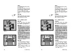
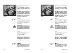
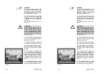
(5) Couvrir la lame de godet et les
dents avec la capot de protection
(5-2/flèche).
(6) Connecter la fiche du capot
de protection à la prise (5-3/flèche).
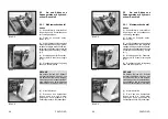
(7) Pousser le transmetteur de
soupape pour l´hydraulique de travail
(4-10/2) au-delà de son point de pous-
sée jusqu´à sa première position.
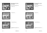
(8) Avec un engin de levage adé-
quat, tel qu'une seconde chargeuse
pivotante avec un godet ajouté, sou-
lever d´autant la flèche porte-godet
de la chargeuse pivotante à remor-
quer, de manière à ce que les
supports de la flèche porte-godet
puissent être insérés (7-1).
(9) Insérer les supports de la
flèche porte-godet (1-1/flèche) et
abaisser la flèche porte-godet
jusqu´aux supports de la flèche
porte-godet.
NOTE
The preparations described in
steps (3), (5) and (6) are only
necessary if the rescue location is
not
on a public road:
(3) Switch the toggle lever for the
steering mode (4-9/4) to the “rear-
wheel steering” position; the
wheels of the front axle must be in
the straight position.
(4) Set the parking brake
(4-10/7).
CAUTION
If the rescue location is on a slope,
wheel chocks must be placed on
the sloping side of both front axle
wheels in addition to applying the
parking brake.
(5) Cover the bucket cutting edge
and teeth with the bucket protector
(5-2/arrow).
(6) Insert the plug of the bucket
protector into the socket (5-3/arrow).
(7) Push the valve lever for the
working hydraulics (4-10/2) beyond
its pressure point into the forward
position.
(8) Using a suitable lifting device,
e.g. a second loader with an attached
bucket, lift the bucket arm of the
loader to be towed until the bucket
arm supports can be inserted into
the loader to be towed (7-1).
(9) Insert the bucket arm supports
(1-1/arrow) and lower the bucket
arm onto the bucket arm supports.
Summary of Contents for AF 100
Page 61: ...F08D F10D F08D F10D Beschilderung Beschilderung Signalisation Signalisation Signs Signs ...
Page 76: ...F08D F10D F08D F10D 2 8 2 8 Schriftzug Lärmarme Baumaschine Schriftzug Lärmarme Baumaschine ...
Page 104: ...F08D F10D F08D F10D Beschreibung Beschreibung Description Description Description Description ...
Page 177: ...F08D F10D F08D F10D Wartung Wartung Entretien Entretien Maintenance Maintenance ...
Page 219: ...F08D F10D F08D F10D Störung Ursache und Abhilfe Störung Ursache und Abhilfe ...
Page 222: ...F08D F10D F08D F10D Dérangements causes et remèdes Dérangements causes et remèdes ...
Page 225: ...F08D F10D F08D F10D Malfunctions causes and remedies Malfunctions causes and remedies ...
Page 228: ...Anhang Anhang Appendice Appendice Appendices Appendices ...
Page 229: ......
Page 230: ......
Page 237: ......
Page 242: ...F08D F10D F08D F10D A 10 3 A 10 3 ...
Page 243: ...F08D F10D F08D F10D B 10 3 B 10 3 ...
Page 244: ...F08D F10D F08D F10D C 10 3 C 10 3 ...
Page 245: ...F08D F10D F08D F10D D 10 3 D 10 3 ...
Page 246: ...F08D F10D F08D F10D E 10 3 E 10 3 ...
Page 247: ...F08D F10D F08D F10D F 10 3 F 10 3 ...

