background image

7-2

K65E/K75D/K95D/K95i

7-2

K65E/K75D/K95D/K95i

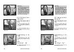
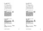
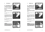
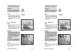
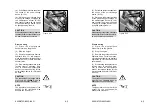
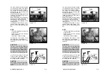
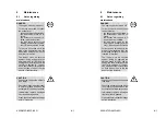
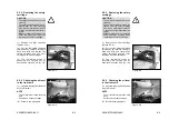
Figure 7-1

7.1.1.1 Towing the articu-
lated loader if the engine has
failed

(1)

Press the toggle switch for the

hazard flasher (4-13/10).
(2)

Set the drive switch (4-12/6) to

position "0".
(3)

Apply the parking brake

(4-12/3).

CAUTION

If the rescue location is on a slope,
wheel chocks must be placed on
the sloping side of both front axle
wheels in addition to applying the
parking brake.

NOTE

The preparations described in steps
(4) and (5) are only necessary if the
rescue location is not on a public
road:

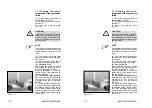
(4)

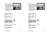
Cover the bucket cutting edge

and teeth with the bucket protector
(5-3/arrow).
(5)

Insert the plug of the bucket

protector into the socket (5-4/arrow).
(6)

Only for AL 70e:

With the ignition turned on, unlock
and actuate the toggle switch for
the floating position (4-13/14).
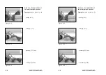
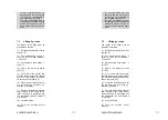
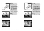
Refer to illustration 7-7 and the
pertaining text if the loader has no
floating position.
(6)

For AL85t / AL100t / AL100ti:

Push the valve lever for the working
hydraulics (4-12/5) beyond its
pressure point into the forward
position.
(7)

Using a suitable lifting device,

e.g. a second articulated loader with
an attached bucket, lift the bucket
arm of the articulated loader to be
towed until the bucket arm support
can be inserted into the loader to be
towed (7-1).

Summary of Contents for AL 100t

Page 1: ...f r Lader AhlmannBaumaschinenGmbH Am Friedrichsbrunnen 2 D 24782 B delsdorf Telefon04331 351 325 Internet www ahlmann baumaschinen de Telefax 04331 351404 E Mail info ahlmann baumaschinen de 1007683A...

Page 2: ...erved by the manufacturer there may be differences in the figures however this has no influence on the technical contents Introduction Preface Ahlmann sswivelshovelloaders articulatedloadersandloadere...

Page 3: ...ions StVZO Stra enverkehrzulassungsordnung German Traffic Regulations opt optional equipment Edition 07 2000 Print 07 2000 How to handle this manual Explanations The designations left and right are to...

Page 4: ...rive 3 1 3 1 6 Axle loads 3 2 3 1 7 Tires 3 2 3 1 8 Steering system 3 2 3 1 9 Brake system 3 2 3 1 10 Electrical system 3 2 Table of contents 1 Fundamental safety instructions 1 1 1 1 Warnings and sym...

Page 5: ...controlled fan 3 9 3 4 Attachments AL 70e 3 10 3 4 1 Buckets 3 10 3 4 2 Fork lift attachment 3 12 3 4 3 Lifting hook 3 12 3 1 11 Hydraulic system 3 3 3 1 12 Fuel supply system 3 3 3 1 13 Heating and...

Page 6: ...ing the operator s seat 5 10 6 Attachments 6 1 6 1 Mounting and dismounting attachments without hydraulic connections 6 1 3 5 Attachments AL 85t 3 14 3 5 1 Buckets 3 14 3 5 2 Fork lift attachment 3 16...

Page 7: ...ttery 8 15 8 2 16 Checking adjusting the service parking brake 8 16 8 2 17 Maintaining replacing the fresh air filter 8 17 6 1 1 Standard lightweight bucket 6 1 6 1 2 Fork lift attachment 6 2 6 1 3 Li...

Page 8: ...c circuit diagram 11 2 1 Hydraulic circuit diagram AL 70e 11 2 2 Hydraulic circuit diagram AL 85t AL 100t AL 100ti 12 Index 9 Malfunctions causes and remedies 9 1 10 Protection against theft 10 1 10 1...

Page 9: ...Safety regulations...

Page 10: ...ss the use of the machine may cause danger for the user or third parties or impairments to the machine or other real values 1 Fundamental safety instruction 1 1 Warningsandsymbols In this operation ma...

Page 11: ...for environment protection must be observed and the personnel must be accordingly Traffic regulations must also be observed 1 2 2 The machine and attach mentsmayonlybeusedinatechnical non objectionabl...

Page 12: ...fluence the safety of the machine stop the machine immediately and inform the competent person in charge about the incident 1 3 3 The personnel in charge of workingwiththemachinemustread the operating...

Page 13: ...e demon strated their ability to their em ployer must be expected to carry out the work conveyed to them in diligent manner 1 3 9 Without the manufacturer s consent do not make any modifications or co...

Page 14: ...tioning 1 5 1 5 Before moving the machine always check that the attachments are safely stowed so that no accident may occur 1 4 2 Electrical work on the machine may only be carried out by a qualified...

Page 15: ...chine byworkattachmentsanddevices by loads swiveling out by loads falling down by attachments falling down from the machine 1 5 1 6 Beforecommencingwork make yourself familiar with the working environ...

Page 16: ...r the safe execution of certain work additio nal lighting must be provided on the working site especially at dumping points 1 5 1 12 In case of danger to persons the operator must give appropriate war...

Page 17: ...sedatstationarydumpingareas when firmly integrated installation areprovidedtopreventthemachine from running or sliding down 1 5 1 20 Should the driver s sight of his driving and working area be restri...

Page 18: ...ized persons from using it 1 5 1 33 The driver must not leave the machine if the attachments are not lowered or safeguarded 1 5 1 27 Avoid such work which could have detrimental effect on the stabilit...

Page 19: ...the attachment is set down on the ground or supported or when equivalent measures against un intentional movement were taken 1 5 1 34 During work brakes and after work hours the driver should endeavor...

Page 20: ...ienced per sonnel should be entrusted with the securing of loads Loads must be secured so that they cannot slip or fall down During maintenance and repair work under the bucket arm the bucket arm supp...

Page 21: ...and make sure that the machine is free from oil fuel oil or dirt Do not use aggressive detergents Use lintless cleaning rags 1 5 2 11 Attached loads may only be moved with the machine when the road is...

Page 22: ...a specialist before commissioning Inaddition itshould be checked after essential modifi cations before it returns to service 1 5 2 18 Before cleaning the machine with water or steam jet high pressure...

Page 23: ...above 1 kV up to 110 kV 3 0 m above 110 kV up to 220 kV 4 0 m above 220 kV up to 380 kV 5 0 m unknown nominal voltage 5 0 m 1 5 2 25 The machine must be checked by a specialist once a year Furthermor...

Page 24: ...reviewed inspected at regular intervals Any defects e g loose connections or scorched cabling must be eliminated immediately When approaching overhead lines all working movements of the machine must b...

Page 25: ...pare parts are ordered 1 6 3 Noise Sound protection equipment must be in protective position during operation of the machine 1 6 1 6 The cable must be disconnectedfromthenegativepole of the battery be...

Page 26: ...rating areas where there is sufficient ventilation The regulations for the respective working site must be strictly observed 1 6 4 Oil grease and other chemical substances 1 6 4 1 The relevant safety...

Page 27: ...e on the ramp without danger of sliding 1 7 5 Restart the machine strictly observing the regulations of the operating manual 1 6 5 2 Only carry out welding burning and grinding work on the machine whe...

Page 28: ...fuse instructions given by third parties when these instructions are detrimental to the safety of the driver and the machine 1 8 Safety information for the contractor or the contrac tor s authorized p...

Page 29: ...in the scope of professional training must not work on with the machine unless they are supervised by an experienced person 1 8 2 4 Personnel who are to be trained instructed or working on with the m...

Page 30: ...Signs...

Page 31: ...CAUTION Use mineral oil DIN 51524 HVLP 46 ISO VG 46 VI 180 via the brake fluid reservoir to the right of the driver s seat 8 Maximum speed 2 Signs 2 1 Warning and information signs 1 Loader type plat...

Page 32: ...0 A 13 Working lights brake light 30 0 A 14 Warning beacon opt signal horn plug socket interior lighting 30 0 A opt optional equipment View on the fuse box 2 2 Fuses 4 13 17 1 Traction drive 10 0 A 2...

Page 33: ...2 open Hydraulic drive stages 4 12 7 Hare symbol fast Snail symbol slow Travel direction 4 12 6 forward 0 backward AL 85t AL 100t AL 100ti AL 70e AL 85t AL 100t AL 100ti AL 70e 2 3 Symbols Hand lever...

Page 34: ...cted articulation area Open only when the engine is not running Fuel tank Hydraulic oil reservoir Lifting points for transportation by crane Stay out of the unprotected articulation area Open only whe...

Page 35: ...ting instructions Make sure that all other users have also read the safety instructions Heating Stay out of the danger zone Fixing eyes for towing and lashing Ballblockvalveforworking auxiliary hydrau...

Page 36: ...14 5 20 3 0 2 5 3 0 bar 12 5 18 3 0 2 5 3 0 bar 335 80 R 18 3 0 3 0 bar 15 5 55 R 18 3 2 2 7 3 2 bar 405 70 R 18 3 0 2 5 3 0 bar 365 70 R 18 3 7 3 0 3 7 bar 405 70 R 18 3 0 2 5 3 0 bar 365 80 R 20 3 0...

Page 37: ...A Acoustic power level AL 100t Type 20 km h Noise in the driver s cabin 99 dB A Acoustic pressure level AL 100t Type 20 km h Noise outside 79 dB A Acoustic power level AL 70e Noise outside 99 dB A Ac...

Page 38: ...tic power level AL 100ti Type 30 km h Noise in the driver s cabin 99 dB A Acoustic pressure level AL 100ti Type 30 km h Noise outside 79 dB A Acoustic power level AL 100t Type 30 km h Noise in the dri...

Page 39: ...Technical data...

Page 40: ...1 3 1 3 Starter 2 2 kW 12 V 3 1 4 Alternator 60 A 14 V 3 1 5 Hydrostatic traction drive Stage I 0 7 km h Stage II 0 20 km h 3 Technical data 3 1 AL70e NOTE The technical data refer to tires of size 33...

Page 41: ...g on the front axle via a spring reservoir and on all four wheels via a cardan shaft 3 1 10 Electrical system Battery 88 Ah 3 1 6 Axleloads Perm axle loads acc to StVZO front 3500 kg rear 4000 kg Perm...

Page 42: ...ndicator Activation pressure p 2 bar 3 1 16 Oil cooler with temperature controlled fan Power max 15 kW Flow rate 23 l min o 3 1 11 Hydraulicsystem Contents 100 l Hydraulic oil reservoir 70 l Flow rate...

Page 43: ...ctiondrive 20 km h model Stage I 0 7 km h Stage II 0 20 km h 30 km h model Gear stage 1 Stage I 0 7 km h Stage II 0 15 km h 3 2 AL85t NOTE The technical data refer to tires of size 365 80 R 20 3 2 1 M...

Page 44: ...ng on the front axle via a spring reservoir and on all four wheels via a cardan shaft 3 2 10 Electricalsystem Battery 88 Ah Gear stage 2 Stage I 0 14 km h Stage II 0 30 km h 3 2 6 Axleloads Perm axle...

Page 45: ...indicator Activation pressure p 2 bar 3 2 16 Oil cooler with temperature controlled fan Power max 15 kW Flow rate 23 l min o 3 2 11 Hydraulicsystem Contents 100 l Hydraulic oil reservoir 70 l Flow ra...

Page 46: ...ctiondrive 20 km h model Stage I 0 7 km h Stage II 0 20 km h 30 km h model Gear stage 1 Stage I 0 7 km h Stage II 0 14 km h 3 3 AL100t NOTE The technical data refer to tires of size 14 5 20 3 3 1 Mach...

Page 47: ...ng on the front axle via a spring reservoir and on all four wheels via a cardan shaft 3 3 10 Electricalsystem Battery 88 Ah Gear stage 2 Stage I 0 15 km h Stage II 0 30 km h 3 3 6 Axleloads Perm axle...

Page 48: ...indicator Activation pressure p 2 bar 3 3 16 Oil cooler with temperature controlled fan Power max 15 kW Flow rate 25 l min o 3 3 11 Hydraulicsystem Contents 100 l Hydraulic oil reservoir 70 l Flow ra...

Page 49: ...oads according to DIN 24094 Bulk density t m 2 0 Rated dump load frontal kg 3240 swiveled kg 2840 Ratedpayload frontal kg 1620 swiveled kg 1420 Operating weight without attachment kg 4620 with water i...

Page 50: ...h swivelled bucket mm 3325 M u l t i p u r p o s e b u c k e t S t a n d a r d b u c k e t L i g h t w e i g h t b u c k e t M u l t i p u r p o s e b u c k e t S t a n d a r d b u c k e t L i g h t w...

Page 51: ...tal kg 2810 swiveled kg 2240 Ratedpayload frontal kg 1405 swiveled kg 1120 Tear out force ISO 8313 daN Pushing force kN 35 3 NOTE The technical data refer to tires of size 405 70 R 18 Buckettype Stand...

Page 52: ...3 14 K65E K75D K95D K95i 3 14 K65E K75D K95D K95i 3 4 2 Fork liftattachment 3 4 3 Liftinghook 3 4 2 Fork liftattachment 3 4 3 Liftinghook...

Page 53: ...ost position 1050 mm FF Min lifting height 825 mm GG Lifting height with maximum reach 1300 mm HH Max lifting height 3950 mm 3 4 2 Fork lift attachment Fork length 1100 mm Fork height 45 mm Fork spaci...

Page 54: ...oads according to DIN 24094 Bulk density t m 2 0 Rated dump load frontal kg 3670 swiveled kg 3230 Ratedpayload frontal kg 1835 swiveled kg 1615 Operating weight without attachment kg 4990 with water i...

Page 55: ...Max dumping distance at max lifting height and swivelled bucket mm 535 HH13Max dumping height with swivelled bucket mm 3385 M u l t i p u r p o s e b u c k e t S t a n d a r d b u c k e t L i g h t w...

Page 56: ...kg 2550 2380 Ratedpayload frontal kg 1550 1455 swiveled kg 1275 1190 Tear out force ISO 8313 daN Pushing force kN 38 0 38 0 NOTE The technical data refer to tires of size 405 70 R 20 Buckettype Stand...

Page 57: ...3 20 K65E K75D K95D K95i 3 20 K65E K75D K95D K95i 3 5 2 Fork liftattachment 3 5 3 Liftinghook 3 5 2 Fork liftattachment 3 5 3 Liftinghook...

Page 58: ...most position 965 mm FF Min lifting height 890 mm GG Lifting height with maximum reach 1350 mm HH Max lifting height 4030 mm 3 5 2 Fork lift attachment Fork length 1100 mm Fork height 45 mm Fork spaci...

Page 59: ...s according to DIN 24094 Bulk density t m 2 0 Rated dump load frontal kg 4170 swiveled kg 3660 Ratedpayload frontal kg 2085 swiveled kg 1830 Operating weight without attachment kg 5320 with water in t...

Page 60: ...Max dumping distance at max lifting height and swivelled bucket mm 530 HH13Max dumping height with swivelled bucket mm 3390 M u l t i p u r p o s e b u c k e t S t a n d a r d b u c k e t L i g h t w...

Page 61: ...3 24 K65E K75D K95D K95i 3 24 K65E K75D K95D K95i 3 6 2 Fork liftattachment 3 6 3 Liftinghook 3 6 2 Fork liftattachment 3 6 3 Liftinghook...

Page 62: ...most position 975 mm FF Min lifting height 880 mm GG Lifting height with maximum reach 1355 mm HH Max lifting height 4015 mm 3 6 2 Fork lift attachment Fork length 1100 mm Fork height 45 mm Fork spaci...

Page 63: ...actiondrive 20 km h model Stage I 0 7 km h Stage II 0 20 km h 30 km h model Gear stage 1 Stage I 0 7 km h Stage II 0 14 km h 3 7 AL 100ti with industrial arm NOTE The technical data refer to tires of...

Page 64: ...ing on the front axle via a spring reservoir and on all four wheels via a cardan shaft 3 7 10 Electricalsystem Battery 88 Ah Gear stage 2 Stage I 0 15 km h Stage II 0 30 km h 3 7 6 Axleloads Perm axle...

Page 65: ...nationindicator Activation pressure p 2 bar 3 7 16 Oilcoolerwithtemperature controlledfan Power max 15 kW Flow rate 25 l min o 3 7 11 Hydraulicsystem Contents 100 l Hydraulic oil reservoir 70 l Flow r...

Page 66: ...t kg 283 Loads according to DIN 24094 Bulk density t m 2 0 Rated dump load frontal kg 3770 swiveled kg 3310 Ratedpayload frontal kg 1885 swiveled kg 1655 Operating weight without attachment kg 5250 wi...

Page 67: ...h swivelled bucket mm 3680 M u l t i p u r p o s e b u c k e t S t a n d a r d b u c k e t L i g h t w e i g h t b u c k e t M u l t i p u r p o s e b u c k e t S t a n d a r d b u c k e t L i g h t w...

Page 68: ...3 32 K65E K75D K95D K95i 3 32 K65E K75D K95D K95i A2 A1 HH17 A2 A1 HH17 3 7 17 2 Fork liftattachment 3 7 17 3 Liftinghook 3 7 17 2 Fork liftattachment 3 7 17 3 Liftinghook...

Page 69: ...most position 865 mm FF Min lifting height 880 mm GG Lifting height with maximum reach 1360 mm HH Max lifting height 4330 mm 3 7 17 2 Fork lift attachment Fork length 1100 mm Fork height 45 mm Fork sp...

Page 70: ...Description...

Page 71: ...of vehicle 9 Driver s cabin 10 Drive motor 11 Rear axle 12 Hydraulic oil reservoir 13 Articulation pivot joint 14 Front axle 15 Quick change device Figure 4 1 4 Description 4 1 Overview 1 Bucket prot...

Page 72: ...Fig 4 2 NOTE All four wheels must be identical and have be same PR rating PR ply rating number of textile plies Figure 4 2 Figure 4 2 4 2 Loader Undercarriage The axial piston pump for the hydraulicd...

Page 73: ...lied The parking brake is actuatedviaahandlever 4 4 arrow located to the right of the operator s seat Figure 4 4 Figure 4 3 Steering system The power for the hydrostatic steering system is supplied vi...

Page 74: ...tric arc welding on the loader is only to be performed when the battery main switch 4 11 3 has been disconnected Figure 4 5 Inching option The inching pedal is located next to the left hand service br...

Page 75: ...ked and actuated DANGER The floating position may only be activated when the bucket is in the lowermost position Figure 4 6 Fuel supply system The fuel tank is located on the right hand side of the lo...

Page 76: ...CAUTION The lifting device suspension must only be used for driving over long distances but not for working with theloader Floating position AL 85t AL 100t AL 100ti The loader is equipped with a floa...

Page 77: ...e quick change device from getting stretched see Fig 4 8a line or from dropping into the bucket arm Figure 4 8 Figure 4 7 Figure 4 8 Figure 4 7 Figure 4 8a Figure 4 8a Bucket position mark Thedriverca...

Page 78: ...d 3 Set the drive switch 4 12 6 to 0 4 Apply the parking brake 4 12 3 5 Turn the ignition key to the left to position 0 5 1 CAUTION Never change the stop settings made at the factory otherwise it may...

Page 79: ...he wheel nuts with a torque wrench to 440 Nm CAUTION Tighten the wheel nuts after the first 8 10 operating hours Figure 4 9 6 Close the ball block valve for the working and auxiliary hydraulics 1 3 ar...

Page 80: ...or working hydraulics 6 Drive switch forward 0 reverse 7 Hydraulic driving steps right speed I slow left speed II fast Figure 4 11 Figure 4 12 Figure 4 10 Figure 4 11 Figure 4 12 Figure 4 10 4 4 Contr...

Page 81: ...ulic oil filter clogging indicator 24 Control lamp for hydraulic oil temperature 25 Control lamp for parking brake 26 Control lamp for directional indicator 27 Control lamp for engine oil pressure Fig...

Page 82: ...Operation...

Page 83: ...perature gauge and the operating hour meter function Start the engine in position 0 of the drive switch 4 12 6 Figure 5 1 5 Operation 5 1 Checksbeforestart up Engine oil level see the ope rat ing inst...

Page 84: ...this reason always use winter diesel fuel suitable for tempe ratures down to 15 C when the outside temperature is below 0 C 5 Turn the ignition key clockwise to position III 5 1 As soon as the engine...

Page 85: ...f an appro priate grade if required Seesection 8 2 12fortheoilchange procedure required for the hydraulic system Figure 5 2 NOTE The fuelling stations normally start offering winter diesel fuel in goo...

Page 86: ...ess a valid driver s license The driver must carry his driving license original and the ope rating permit original with him 5 2 2 4 Anti freezing agent for the windshield washer system CAUTION If the...

Page 87: ...9 Setthegearshiftto II 4 13 13 only for fast loaders 30 km h 10 Preselect the travel direction 4 12 6 Figure 5 4 Figure 5 3 Before driving on public roads the following safety measures must be taken 1...

Page 88: ...stage I 4 12 7 can be selected The travel speed can thus be reduced to 6 km h AL 70e or 7 km h AL 85t AL 100t and AL 100ti 11 Presstheacceleratorpedal 4 10 3 NOTE The loader starts The travel speed i...

Page 89: ...ll throttle in favour of the thrust force The thrust forces and travel speeds are the same in forward and reverse direction To attain full performance the combined action of propulsion and of the work...

Page 90: ...e side NOTE Lever to the front warm Lever to the side cold 2 Adjust the amount of air as described under 5 2 5 1 Figure 5 5 Figure 5 6 Figure 5 7 Figure 5 5 CAUTION Thehydraulicquick changedevice must...

Page 91: ...to position 0 5 1 and remove the key NOTE In position P the parking light and the dashboard illumination remain switched on 5 3 Stoppingloader operation 5 3 1 Parking the loader 1 Stop the loader on s...

Page 92: ...n the horizontal direction to suit the driver s requirements by pulling the handle 5 9 2 upwards and moving the seat forward or backward Figure 5 9 Figure 5 8 5 3 3 Switching off the heating and venti...

Page 93: ...Attachments...

Page 94: ...e must be in the bore holes of the bucket suspension and must be clearly visible 6 3 arrow Figure 6 2 Figure 6 3 Figure 6 1 6 Attachments 6 1 Mounting and dis mounting attachments with out hydraulic c...

Page 95: ...ttachment Positionbothforktinesatanequal distance from the centre 6 6 arrows and lock them Figure 6 5 Figure 6 6 Figure 6 4 Figure 6 5 Figure 6 6 Figure 6 4 Dismounting 1 Place the bucket firmly on th...

Page 96: ...een mounted NOTE The type plate is on the upper side of the crane hook support on the right hand side Figure 6 8 Figure 6 7 Figure 6 8 Figure 6 7 Moving loads on the forks is only permitted close to t...

Page 97: ...hydraulic lines For this purpose movethehandleverfortheauxiliary hydraulics 4 12 1 back and forth several times Figure 6 11 Figure 6 9 Figure 6 10 6 2 Mounting and dis mounting attachments with a hydr...

Page 98: ...tachment has been mounted NOTE The type plate is on the rear of the bucket on the right hand side beneath the cross arm Figure 6 12 Figure 6 12 8 Pullofftheprotectivecapsfrom the hoses of the quick ch...

Page 99: ...bucket can be used for peeling 6 13 scraping 6 14 grabbing 6 15 and in bucket operation Figure 6 13 Figure 6 14 Figure 6 15 Notes on the application of the multi purpose bucket The multi purpose bucke...

Page 100: ...passive driving safety The manufacturer cannot be held responsible for damage that occurs through the use of such products 6 3 Using other attach ments DANGER 1 Only those attachments de scribed in t...

Page 101: ...Rescue towing lashing lifting by crane...

Page 102: ...re of the entire hydraulic system or if only the drive has failed and the engine can drive the rest of the hydraulic system 7 Rescue towing lashing lifting by crane 7 1 Rescue towing lash ing 7 1 1 Re...

Page 103: ...cket arm of the articulated loader to be towed until the bucket arm support can be inserted into the loader to be towed 7 1 Figure 7 1 7 1 1 1Towing the articu lated loader if the engine has failed 1...

Page 104: ...16 Screw in the screw plugs with an O ring into the housing CAUTION After towing has been completed restore the operating state of the brake Figure 7 4 Figure 7 3 Figure 7 2 8 Insert the bucket arm s...

Page 105: ...load of the lashing points load bearing points 7 2 1 and 7 6 1 is 2 0 t at an assumed bracing angle of 45 Figure 7 5 Figure 7 6 17 Switch the hydrostatic drive motor to free oil flow before towing For...

Page 106: ...cation is not on a public road 4 Cover the bucket cutting edge and teeth with the bucket protector 5 3 arrow Figure 7 7 NOTE If the loader has been out of op eration for a longer period of time or if...

Page 107: ...km For a longer distance the defec tive loader must be loaded onto a truck for the lashing points see 7 2 1 7 2 2 and 7 6 1 5 Insert the plug of the bucket protectorintothesocket 5 4 arrow 6 Lift the...

Page 108: ...ert the bend in protection into the articulated link and fasten it 1 4 arrow 8 Lock the doors 9 Fold the outside mirror inwards The max permissible load of the shunting and towing coupling 7 2 2 is 4...

Page 109: ...he loader 7 9 arrows and 7 10 arrows DANGER The lifting gear must have a lifting capacity of at least 3 0 t Figure 7 8 Figure 7 10 Figure 7 9 CAUTION The following items must be observed when lifting...

Page 110: ...Maintenance...

Page 111: ...ning of axles 385 Nm 3 2 Check fastening of cardan shaft 49 Nm 4 Wheels and tyres 4 1 Check air pressure 4 2 Check fastening of wheel nuts 440 Nm 5 Hydraulic system 5 1 Oil level check view glass 5 2...

Page 112: ...owestposition Immediately replace damaged filter inserts and gaskets Clean pressure lubrication fittings before lubricating 8 Maintenance 8 1 Notes regarding maintenance DANGER The engine must be turn...

Page 113: ...lter must be carried out every 500 operating hours The fuel prefilter must be replaced when soiled but at least once a year NOTE For the maintenance work re quired refer to the maintenance plan page 8...

Page 114: ...l out the filter cartridge 8 3 arrow by carefully turning it back and forth 4 Clean the filter cartridge Figure 8 1 Figure 8 3 Figure 8 2 1 Open the engine hood 2 Loosen the two clamps in front of and...

Page 115: ...d becomes clear CAUTION Check all connection pipes and hoses of the air filter system for damage before starting the engine CAUTION For cleaning use a compressed air gun to which a pipe angled at 90 h...

Page 116: ...the axle arch 8 5 arrow NOTE The oil level must reach the plug bore Collect any oil that escapes 2 Screw in the plug again Figure 8 4 Figure 8 5 8 2 5 Replacing the safety cartridge CAUTION The safet...

Page 117: ...oil level reaches the marked level and remains stable 5 Screw in the plug 8 7 arrow again Figure 8 6 Figure 8 7 Figure 8 8 8 2 7 Changing the oil in the front axle 1 Place a sufficiently large oil dr...

Page 118: ...oil level must reach the plug bore Remove any oil that escapes 2 Screw in the plug again Figure 8 9 Figure 8 10 Figure 8 11 8 2 8 Checking the oil level in the rear axle 8 2 8 1Slow loader 20 km h 1 U...

Page 119: ...pollution 3 Screw in the plugs for the axle arch 8 13 2 and the intermediate gear 8 14 2 again Figure 8 13 Figure 8 14 Figure 8 12 3 Unscrew the plug from the distribution gear 8 12 arrow NOTE The oi...

Page 120: ...in the oil CAUTION Waste oil must be disposed of in such a way that it will not cause pollution Figure 8 16 Figure 8 15 Figure 8 17 4 Fill oil into the plug bore of the intermediate gear 8 14 1 until...

Page 121: ...The vent valve of the axle 8 18 arrow must be free from dirt 7 Screw in the plug for the axle arch 8 16 1 again Figure 8 18 3 Screw in the plugs for the axle arch 8 16 2 and the distribution gear 8 1...

Page 122: ...oil via the plug bore until the oil level reaches the opening 6 Screw in the plug with a new gasket Figure 8 20 Figure 8 19 8 2 10 Checking the oil level in the planetary gear 1 Move the loader until...

Page 123: ...for the service parking brake 7 Check the oil level at the sight glass 8 22 2 8 Close the filling nozzle Figure 8 21 Figure 8 22 Figure 8 21 Figure 8 22 8 2 12 Changing the oil in the hydraulic system...

Page 124: ...the lid of the hydraulic oil filter 6 Install the maintenance plate and the bottom cover Figure 8 24 Figure 8 23 Figure 8 25 8 2 13 Replacing the hydraulic oil filter insert CAUTION Replace the filter...

Page 125: ...rating hours NOTE The bolts must be lubricated on both sides of the multi purpose bucket Figure 8 26 Figure 8 27 Figure 8 28 8 2 14 Lubrication points NOTE The lubrication points are marked in red on...

Page 126: ...ening them 8 Installation is in the reverse order DANGER Make sure the fastenings are secure Figure 8 30 Figure 8 31 Figure 8 29 CAUTION Thebearingboltsofthemulti purpose bucket 8 29 arrows must be lu...

Page 127: ...34 b between the sleeve and the sunk face of the housing DANGER The brake must be readjusted if the play is larger than 2 mm Figure 8 32 Figure 8 34 Figure 8 33 8 2 16 Checking adjusting the service p...

Page 128: ...element 8 36 arrow and clean it using compressed air CAUTION Do not use any petrol hot fluids or compressed air for cleaning Figure 8 35 Figure 8 36 Readjustment 6 Pull off the sleeves 8 33 2 and 8 3...

Page 129: ...replaced when it is damaged but at least every 1500 operating hours 5 Insert the filter element and install the heater cover 4 Check the filter element for damage NOTE The filter element must be repla...

Page 130: ...Malfunctions causes and remedies...

Page 131: ...e priority is stuck valve 9 Malfunctions causes and remedies NOTE Malfunctions may only be remedied by authorised personnel Malfunction Possible cause Remedy Engine See the operating instructions for...

Page 132: ...Remove the pressure in the lines by moving the valve lever for the auxiliary hydraulics 4 12 1 back and forth several times Malfunction Possible cause Remedy Defect in the drive Filter is clogged Repl...

Page 133: ...Protection against theft...

Page 134: ...until the tines of the bucket the tines of the fork lift attachment or the boom of the lifting hook is placed on the ground Figure 10 2 Figure 10 3 Figure 10 1 10 Protection against theft Instances w...

Page 135: ...the new stricter requirements of the insurance companies Ask your insurance company for the appropriate details Figure 10 4 Figure 10 4 4 Close the ball block valve for the working and auxiliary hydr...

Page 136: ...Appendices...
Page 137: ...trisch schakelschema El oversigt Diagrama de conexiones el ctricas Elektrisk koblingsskjema 12 13 14 15 16 17 18 21 20 19 23 24 25 26 27 28 30 31 34 35 37 38 39 40 41 42 43 45 46 47 48 49 50 51 52 54...

Page 138: ...amm Elektrisch schakelschema El oversigt Diagrama de conexiones el ctricas Elektrisk koblingsskjema 68 69 70 71 72 73 74 75 76 77 78 79 80 81 83 84 82 89 90 91 92 93 94 96 97 98 99 100 102 103 104 105...

Page 139: ...1 Starter motor 62 Battery main switch 63 Battery 64 Indicator light unit 65 Operating hour meter 66 Engine oil temperature display 67 Fuel level display 01 Starter switch 02 Start blocking relay 03 S...

Page 140: ...rking light rear right 115 Working light front left opt 116 Working light front right opt 117 Relay oil cooler 118 Fuse oil cooler opt optional equipment 68 Activation of working lights 69 Fuse chapte...

Page 141: ...1 4 G1 4 G1 4 G1 4 M12x1 5 M12x1 5 G1 4 G1 4 G1 4 G1 4 G1 4 G1 4 G1 4 G1 4 T P M10x1 G1 2 EF G1 2 CF G1 4 G1 2 P LS SAE 1 T M12x1 5 M14x1 5 M18x1 5 SAE 1 A U G T 0 03 bar 0 35 bar 10 muem 2 bar M12x1...

Page 142: ...1 2 EF G1 2 CF G1 4 G1 2 P LS SAE 1 T M12x1 5 M14x1 5 M18x1 5 SAE 1 A U G T 0 03 bar 0 35 bar 10 muem 2 bar M12x1 5 P1 B1 A B2 10 muem 0 5 bar 0 05 bar 125 muem 130 muem 2 5 bar M22x1 5 M12x1 5 3 bar...

Page 143: ...Pr fhinweise f r Schaufellader A Sachkundigenpr fung nach VBG 40 50 Lader Baggerlader und Bagger Rad und Kettenmaschinen 11 3 Muster Pr fhinweise f r Schaufellader Sachkundigenpr fung nach VBG 40 50...

Page 144: ...er Pr fhinweise f r Schaufellader Sachkundigenpr fung nach VBG 40 50 Lader Baggerlader und Bagger Rad und Kettenmaschinen 11 3 Muster Pr fhinweise f r Schaufellader Sachkundigenpr fung nach VBG 40 50...

Page 145: ...er Pr fhinweise f r Schaufellader Sachkundigenpr fung nach VBG 40 50 Lader Baggerlader und Bagger Rad und Kettenmaschinen 11 3 Muster Pr fhinweise f r Schaufellader Sachkundigenpr fung nach VBG 40 50...

Page 146: ...er Pr fhinweise f r Schaufellader Sachkundigenpr fung nach VBG 40 50 Lader Baggerlader und Bagger Rad und Kettenmaschinen 11 3 Muster Pr fhinweise f r Schaufellader Sachkundigenpr fung nach VBG 40 50...

Page 147: ...er Pr fhinweise f r Schaufellader Sachkundigenpr fung nach VBG 40 50 Lader Baggerlader und Bagger Rad und Kettenmaschinen 11 3 Muster Pr fhinweise f r Schaufellader Sachkundigenpr fung nach VBG 40 50...

Page 148: ...er Pr fhinweise f r Schaufellader Sachkundigenpr fung nach VBG 40 50 Lader Baggerlader und Bagger Rad und Kettenmaschinen 11 3 Muster Pr fhinweise f r Schaufellader Sachkundigenpr fung nach VBG 40 50...

Page 149: ...Fernlicht 4 11 Feststellbremse 4 11 Fettschmierstellen 8 14 Fahrerkabinent r 8 14 Mehrzweckschaufel 8 14 Motorabdeckhaube 8 14 Index A Achslasten 3 2 3 5 3 8 3 24 Anbauger te 6 1 Lasthaken 6 3 Mehrzw...

Page 150: ...8 9 Hydraulikanlage 8 12 Motor 8 2 Planetengetriebe 8 11 Verteilergetriebe Siehe auch lwechsel Hinterachse Schnell ufer 30 km h Feuerl scher 1 19 Freigabe Schnellwechsel vorrichtung 4 11 Frischluftfi...

Page 151: ...ln 8 15 Winterbetrieb 5 2 Frostschutz f r Scheiben waschanlage 5 4 Kraftstoff 5 2 Motor lwechsel 5 3 lwechsel Hydraulikanlage 5 3 Vorderachse 8 6 Vorsatzgetriebe Siehe auch lwechsel Hinterachse Langsa...

Reviews: