4-6
K65C/K75C/K95C
4-6
K65C/K75C/K95C
Pipe break safety device
(option)
A pipe break safety valve is installed
underneath each lift and tip cylin-
der. In the event of a pipe or hose
break in the lift and/or tip system,
the movements of the bucket arm
and the tipping rod are blocked until
the damage is repaired.
Tipping interlock
(option)
The tipping interlock only functions
when the fork-lift attachment has
been installed. It prevents the fork
from tipping down. This function
can be bypassed by pressing the
appropriate pushbutton on the
dashboard.
Lifting device suspension
(option)
When the loader must be driven
over larger distances, especially
with a loaded bucket, the lifting
device suspension (4-13/15) should
be activated to avoid resonant
motion. This becomes even more
important with increasing uneven-
ness of the terrain and increasing
speed of the loader.
CAUTION
The lifting device suspension must
only be used for driving over long
distances, but not for working with
the loader.
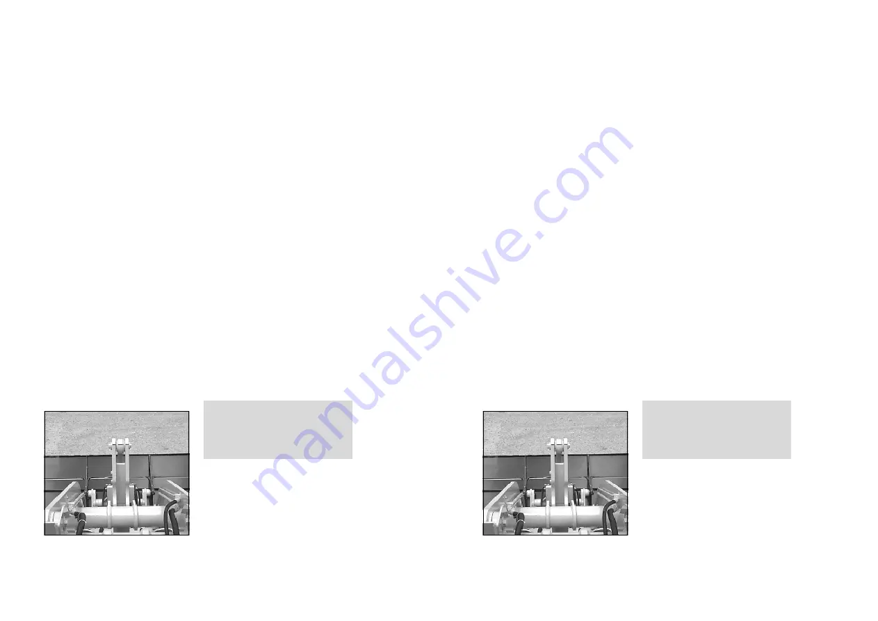
Bucket position mark
The driver can see the position of
the bucket by the coloured mar-
kings on the reversing rod and the
reversing lever. When the coloured
marks (4-7/arrow) form a line, the
bucket floor is parallel to the ground.
Figure 4-7
Summary of Contents for AL 65
Page 8: ...Safety regulations...
Page 29: ...Signs...
Page 38: ...Technical data...
Page 60: ...Description...
Page 72: ...Operation...
Page 83: ...Attachments...
Page 91: ...Rescue towing lashing lifting by crane...
Page 100: ...Maintenance...
Page 120: ...Malfunctions causes and remedies...
Page 123: ...Protection against theft...
Page 126: ...Appendices...
Page 127: ......
Page 128: ......
Page 131: ......
Page 134: ...K65C K75C K95C K65C K75C K95C B B...
Page 135: ...K65C K75C K95C K65C K75C K95C C C...
Page 136: ...K65C K75C K95C K65C K75C K95C D D...
Page 137: ...K65C K75C K95C K65C K75C K95C E E...
Page 138: ...K65C K75C K95C K65C K75C K95C F F...


