7-4
K65C/K75C/K95C
7-4
K65C/K75C/K95C
1
2
1
2
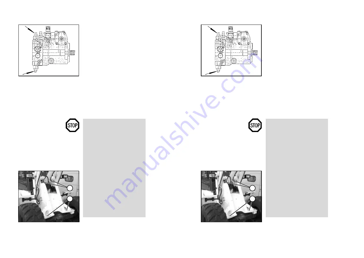
(17) Switch the hydrostatic drive
motor to free oil flow before towing.
For this purpose, screw in the set-
screws at both high pressure relief
valves (7-5/arrows) of the drive pump
until they are level with the hexagon
nuts (size 13) loosened beforehand.
Then tighten the hexagon nuts.
NOTE
After towing has been completed,
loosen the hexagon nuts again.
Screw the setscrews out of both
high pressure relief valves until they
stop. Tighten the lock nuts.
(18) Remove the chocks (if
applicable).
DANGER
- More power is required to steer if
the engine has failed.
- Tow the loader at walking speed
(2 km/h).
- The towing distance should not
exceed 1 km.
- For a longer distance, the defec-
tive loader must be loaded onto a
truck (for the lashing points, see
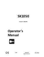
7-2/1, 7-2/2 and 7-6/1).
- The max. permissible load of
the shunting and towing
coupling (7-2/2) is 4.5 t hori-
zontally in the longitudinal
direction.
- The max. permissible load of
the lashing points/load-bearing
points (7-2/1 and 7-6/1) is 2.0 t
at an assumed bracing angle
of 45°.
Figure 7-5
Figure 7-6
Summary of Contents for AL 65
Page 8: ...Safety regulations...
Page 29: ...Signs...
Page 38: ...Technical data...
Page 60: ...Description...
Page 72: ...Operation...
Page 83: ...Attachments...
Page 91: ...Rescue towing lashing lifting by crane...
Page 100: ...Maintenance...
Page 120: ...Malfunctions causes and remedies...
Page 123: ...Protection against theft...
Page 126: ...Appendices...
Page 127: ......
Page 128: ......
Page 131: ......
Page 134: ...K65C K75C K95C K65C K75C K95C B B...
Page 135: ...K65C K75C K95C K65C K75C K95C C C...
Page 136: ...K65C K75C K95C K65C K75C K95C D D...
Page 137: ...K65C K75C K95C K65C K75C K95C E E...
Page 138: ...K65C K75C K95C K65C K75C K95C F F...


